75
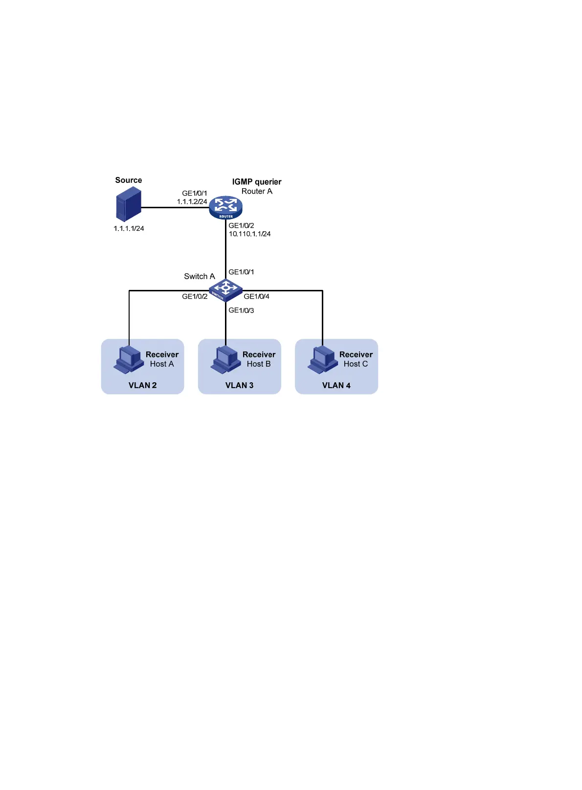
and Host C are receivers of the multicast group, and the hosts belong to VLAN 2 through VLAN 4
respectively.
Configure the port-based multicast VLAN feature on Switch A so that Router A just sends multicast data
to Switch A through the multicast VLAN and Switch A forwards the multicast data to the receivers that
belong to different user VLANs.
Figure 25 Network diagram
Configuration procedure
1. Configure the IP address and subnet mask for each interface as per Figure 25. (Details not shown.)
2. On Router A, enable IP multicast routing, enable PIM-DM on each interface, and enable IGMP on
the host-side interface GigabitEthernet 1/0/2.
<RouterA> system-view
[RouterA] multicast routing-enable
[RouterA] interface gigabitethernet 1/0/1
[RouterA-GigabitEthernet1/0/1] pim dm
[RouterA-GigabitEthernet1/0/1] quit
[RouterA] interface gigabitethernet 1/0/2
[RouterA-GigabitEthernet1/0/2] pim dm
[RouterA-GigabitEthernet1/0/2] igmp enable
3. Configure Switch A:
# Enable IGMP snooping globally.
<SwitchA> system-view
[SwitchA] igmp-snooping
[SwitchA-igmp-snooping] quit
# Create VLAN 10, assign GigabitEthernet 1/0/1 to VLAN 10, and enable IGMP snooping in this
VLAN.
[SwitchA] vlan 10

 Loading...


