Chapter 8 Hardware Reference
© 2017 Harmonic Inc. All rights reserved. 234 Harmonic MediaGrid Release 4.1
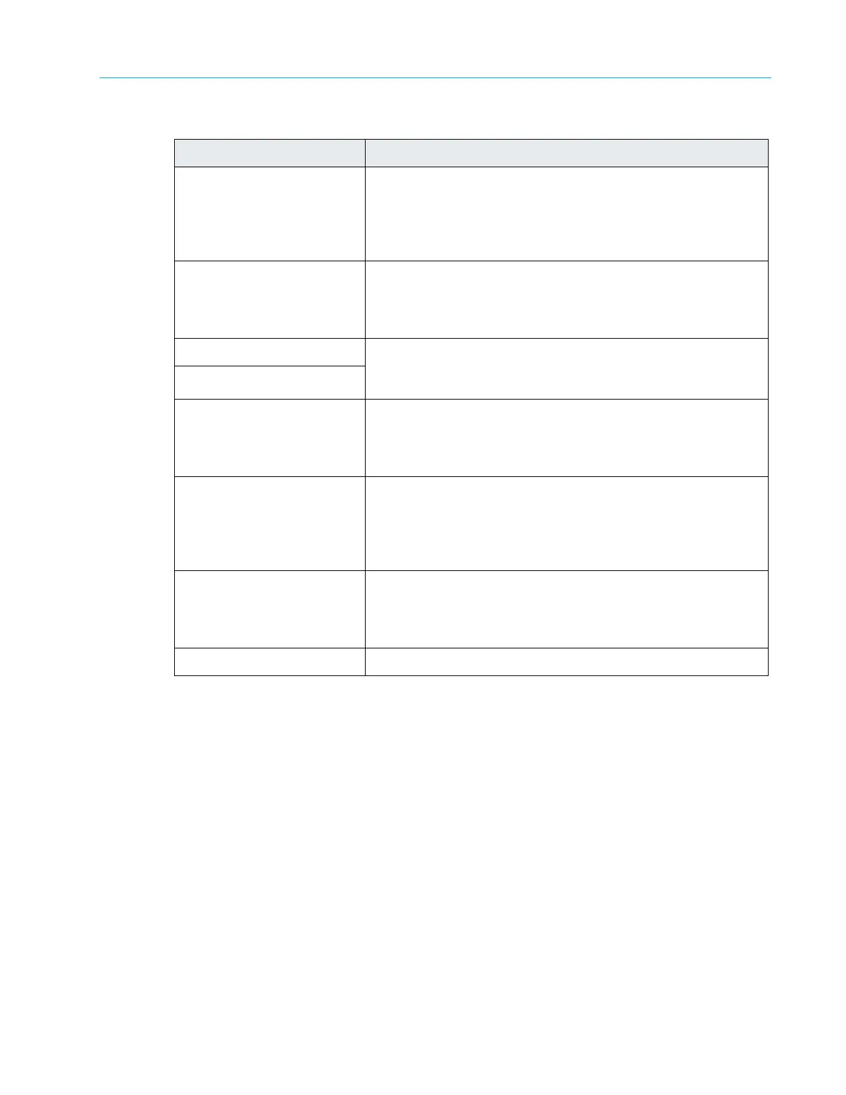
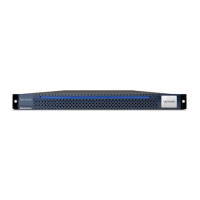
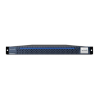
ContentBridge 2010F
Table 8–12: Control Panel Indicators
Button and/or Indicator Description
1. System ID button with
inte
grated LED
The identification button can be used to locate a particular
system within a rack. When this button is pressed, the ID LEDs
on the front panel and on the back edge of the server board
(viewable from the rear panel) flash until the button is pressed
again.
2. Non-maskable interrupt
(NMI) button (recessed, tool
required for use)
The NMI button can be used to put the server into a halt state
when diagnosing an issue. To prevent an accidental system
halt, the physical button is located behind the Control Panel
and is only accessible with the use of a small tipped tool.
3. NIC 0 Activity LED When a network link is detected,
the
LED will turn on solid. The
LED blinks when data is being sent or received over the
network.
4. NIC 1 Activity LED
5. System cold reset button
(recessed,
tool required for
use)
When pressed, this button initializes a hard system reset. To
prevent an accidental reset, the physical button is located
behind the Control Panel and is only accessible with the use of
a small tipped tool.
6. System status LED
Shows the current health of the server system. A second
system status LED is located on the back edge of the server
board and is viewable from the rear panel. Both LEDs will show
the same state. Refer to
Table 8–13 for a description of each
LED state.
7. Power/Sleep button with
inte
grated LED
Toggles the power on and off. The power-on indicator lights
green when the system power is on. When the power-on
indicator is off, this indicates that no power is supplied to the
system.
8. Drive activity LED Indicates drive activity.