Chapter 8 Hardware Reference
© 2017 Harmonic Inc. All rights reserved. 233 Harmonic MediaGrid Release 4.1
ContentBridge 2010F
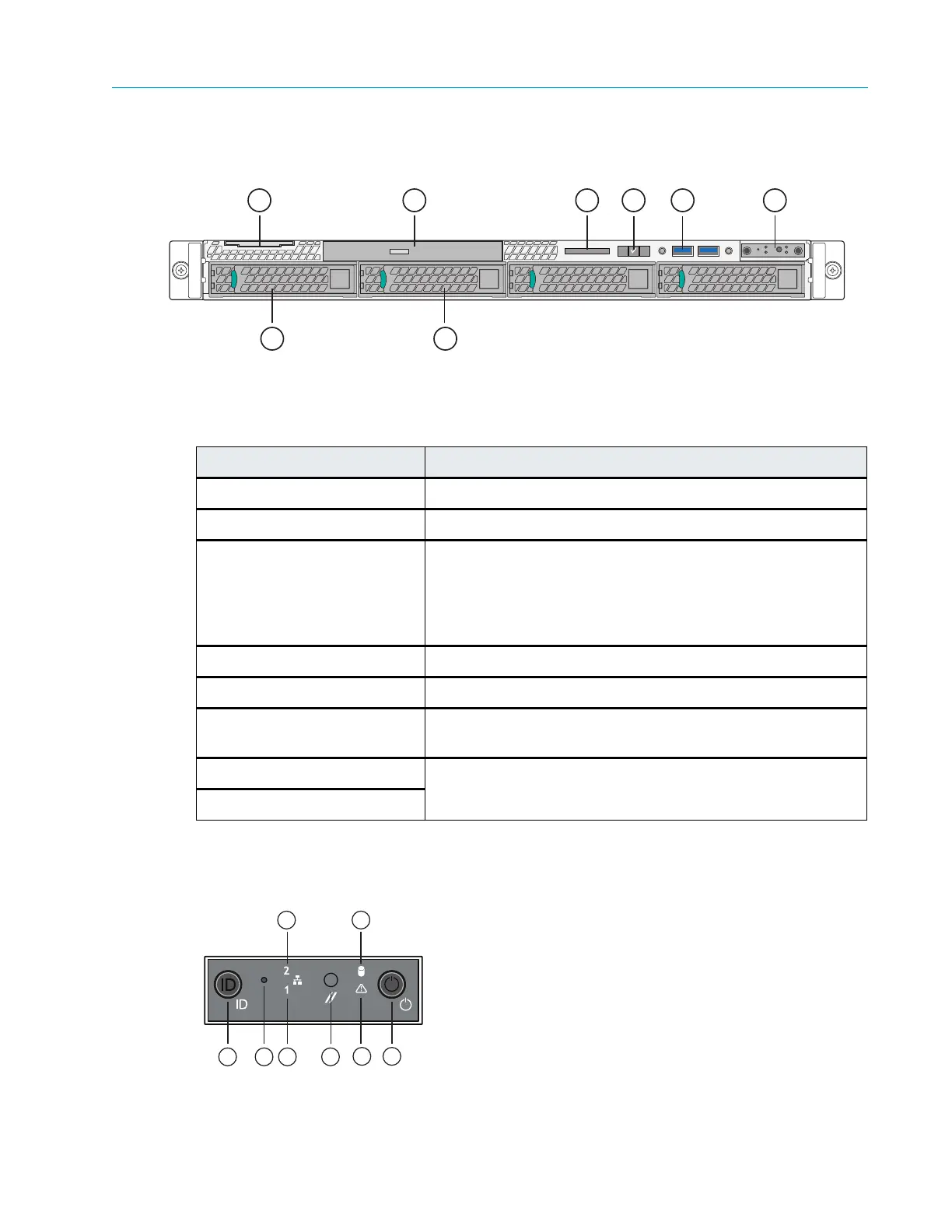
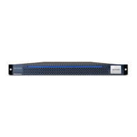
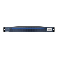
Figure 8–12 and Table 8–11 detail the front panel view of a typical ContentBridge 2010F with the
bezel removed. Note that your ContentBridge 2010F may differ somewhat from the one
described below.
Figure 8–12: Front View of ContentBridge 2010F
Control Panel Indicators
Figure 8–13 and Table 8–12 describe the Control Panel buttons and LED states.
Figure 8–13: Control Panel Indicators
Table 8–11: ContentBridge 2010F Front Panel Components
Indicator, Button, or Connector Description
1.System label pull-out tab Use to apply a product number and/or serial number label.
2. Optical drive Use for software installation.
3. LCD display Displays system ID, status information, and system error
me
ssages. The LCD lights blue during normal system
operation. The LCD lights amber when the system needs
attention, and the LCD panel displays an error code followed
by descriptive text.
4. LCD menu buttons Allow you to navigate the control panel LCD menu.
5. USB connectors (2) Use to connect the front bezel.
6. Control panel Refer to Figure 8–12 for a description of control panel buttons
and indicators.
7. Solid state drive 0 Refer to Table 8–14 for a description of the indicator codes.
8. Solid state drive 1