Appendix A Legacy Hardware Platforms
© 2017 Harmonic Inc. All rights reserved. 323 Harmonic MediaGrid Release 4.1
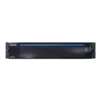
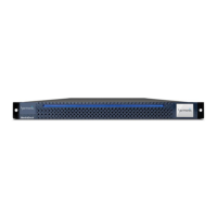
ContentBridge 2010E
Figure 9–11: Front View of ContentBridge 2010E
Figure 9–12 and T
able 9–13 describe the typical hard drive indicators and their functions.
Table 9–12: ContentBridge 2010E Front Panel Components
Indicator, Button, or Connector Description
1. Power-on indicator/button The power button controls the DC power supply output
to the sys
tem.
The power-on indicator lights when the system power is
on. Wh
en the power-on indicator is off, this indicates that
no power is supplied to the system.
2. System identification button The identification buttons on the
front and back panels
can be used to locate a particular system within a rack.
When one of these buttons is pressed, the ID buttons on
the front and rear panels flash until one of the buttons is
pressed again.
Press to toggle the system ID on and off.
3. Video Connector Connects a monitor to the system.
4. LCD menu buttons Allows you to navigate the control panel
LCD menu.
5. LCD display Displays system ID, status information, and system error
me
ss
ages. The LCD lights blue during normal system
operation. The LCD lights amber when the system needs
attention, and the LCD panel displays an error code
followed by descriptive text.
6. USB connectors Use to connect the front bezel.
7. Optical drive Use for software installation.
8. Hard drive 0 Refer to Table 9–13 for a description of the indicator
codes.
9. Hard drive 1
5
2
4
7
6
8 9
<
>
1
3