Appendix A Legacy Hardware Platforms
© 2017 Harmonic Inc. All rights reserved. 325 Harmonic MediaGrid Release 4.1
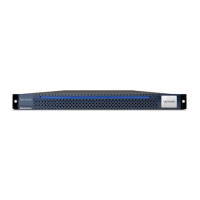
ContentBridge 2010E
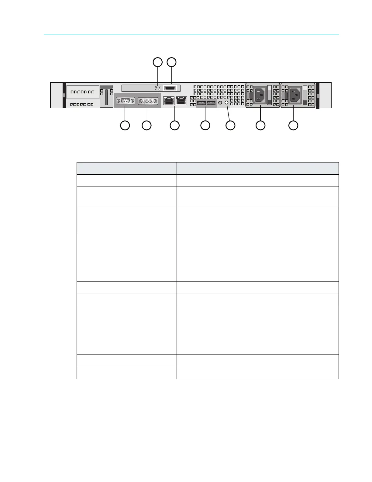
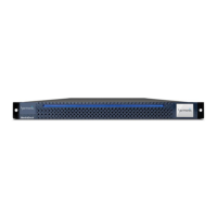
Figure 9–13: Rear View of ContentBridge 2010E
10 Gigabit Ethernet LEDs
Figure 9–14 and Table 9–15 describe the possible states of the 10 Gigabit Ethernet LEDs.
Table 9–14: ContentBridge 2010E Rear Panel Components
Indicator, Button, or Connector Description
1. Serial connector Use to connect a serial device to the system
2. Video connector Use to connect a monitor to the system (for maintenance
only).
3. 10 Gigabit Ethernet LEDs The LEDs show the state of the 10 Gigabit Ethernet
connector.
For a description of the LEDs and possible
states, refer to Figure 9–14 and Table 9–15.
4. 10 Gigabit Ethernet connector Use to connect the ContentBridge to the customer
network
switch.
The Link light does not appear until the Configuration
Assist
ant is completed for the ContentBridge. Refer to
About Harmonic MediaGrid Configuration for more
information.
5. Gigabit Ethernet ports NIC 0 (left) and NIC 1 (right)
6. USB connectors (2) Used for maintenance purposes only.
7. System identifica
tion button/
indicator
Both the SystemManager application and the system
identification buttons on the front and back panels can be
used to locate a particular system within a rack. When
one of these buttons is pressed, the ID buttons on the
front and rear panels blink until one of the buttons is
pressed again.
8. Power supply 1 Dual redundant power supplies pr
ovide
power to the
system.
9. Power supply 2
1
2
7 8
6
9
43
5