P/N MAN-01964 Revision 001 ix
DRAFT
Preview copy—Generated 7/9/2010
User Manual
List of Figures
List of Figures
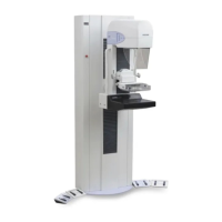
Figure 1-1: Selenia Dimensions .................................................................................................................... 1
Figure 1-2: Label Locations........................................................................................................................... 8
Figure 2-1: System Power Controls ............................................................................................................... 9
Figure 2-2: Acquisition Workstation Controls and Displays ........................................................................ 10
Figure 2-3: Tubestand Controls and Indicators............................................................................................ 12
Figure 2-4: C-arm Controls ......................................................................................................................... 13
Figure 2-5: Compression Device................................................................................................................. 13
Figure 2-6: Compression Display................................................................................................................ 13
Figure 2-7: Tubehead Display..................................................................................................................... 14
Figure 2-8: Dual Function Footswitches...................................................................................................... 14
Figure 2-9: The Startup Screen.................................................................................................................... 15
Figure 2-10: How to Log In......................................................................................................................... 16
Figure 2-11: C-arm Controls (left side shown) ............................................................................................. 17
Figure 2-12: Power Buttons ........................................................................................................................ 23
Figure 3-1: An Example Select Function to Perform Screen......................................................................... 25
Figure 3-2: An Example Gain Calibration Screen ........................................................................................ 26
Figure 3-3: How to Select a Patient............................................................................................................. 27
Figure 3-4: How to Add a New Patient ....................................................................................................... 28
Figure 3-5: The Filter Tab in the Patient Filter Screen.................................................................................. 29
Figure 3-6: An Example Generator Tab in the Procedure Screen................................................................. 31
Figure 3-7: The Add View Screen ............................................................................................................... 33
Figure 3-8: The Add Procedure Dialog Box ................................................................................................ 34
Figure 3-9: The Edit View Screen................................................................................................................ 34
Figure 3-10: The Print Screen ..................................................................................................................... 37
Figure 4-1: The Preview Screen .................................................................................................................. 41
Figure 4-2: The Tools Tab in the Procedure Screen..................................................................................... 42
Figure 4-3: Marked Images in a Procedure.................................................................................................. 42
Figure 4-4: Image Review Tools.................................................................................................................. 43
Figure 4-5: Image Review Tabs................................................................................................................... 44
Figure 4-6: Icons Available on the Notices Tab........................................................................................... 44
Figure 4-7: The Exposure Index .................................................................................................................. 44
Figure 5-1: C-arm Accessories .................................................................................................................... 47
Figure 5-2: How to Install the Conventional Face Shield............................................................................. 48
Figure 5-3: How to Align the Retractable Face Shield on the C-arm............................................................ 49
Figure 5-4: Installation................................................................................................................................ 50
Figure 5-5: Operation ................................................................................................................................. 50
Figure 5-6: How to Install a Compression Paddle ....................................................................................... 53
Figure 5-7: How to Remove the Compression Paddle ................................................................................. 53
Figure 5-8: The FAST Compression Mode Slide .......................................................................................... 54
Figure 5-9: Installation of the Magnification Stand ...................................................................................... 55
Figure 5-10: How to Attach the Localization Crosshair Device ................................................................... 56
Figure 5-11: How to Install and Remove the Magnification Crosshair Device ............................................. 57
Figure 6-1: Screening Example, Conventional Procedure............................................................................ 60
Figure 8-1: The Admin Screen .................................................................................................................... 68
Figure A-1: Tubestand Dimensions ............................................................................................................. 73
Figure A-2: Acquisition Workstation Dimensions........................................................................................ 74