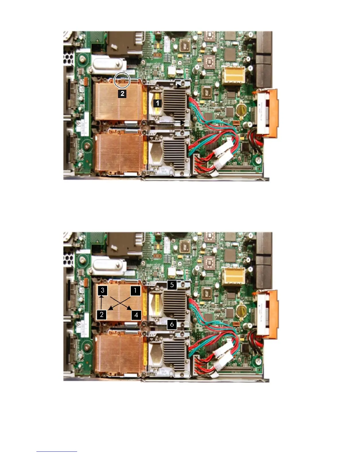
Figure 54 Uncovering the ZIF Socket
6. Tighten the captive shoulder screws (1 - 4) on the processor heat sink in the order shown in
Figure 55 (page 128) with the Torx T-15 screwdriver.
7. Tighten the captive screws (5 - 6) on the processor with the Torx T-15 screwdriver.
Figure 55 Installing a Processor in Slot 1
8. Connect the power cable to the power connector on the processor.
9. Install the right access panel.
See “Replacing the Right Access Panel” (page 117).
128 Removing and Replacing Components
 Loading...


