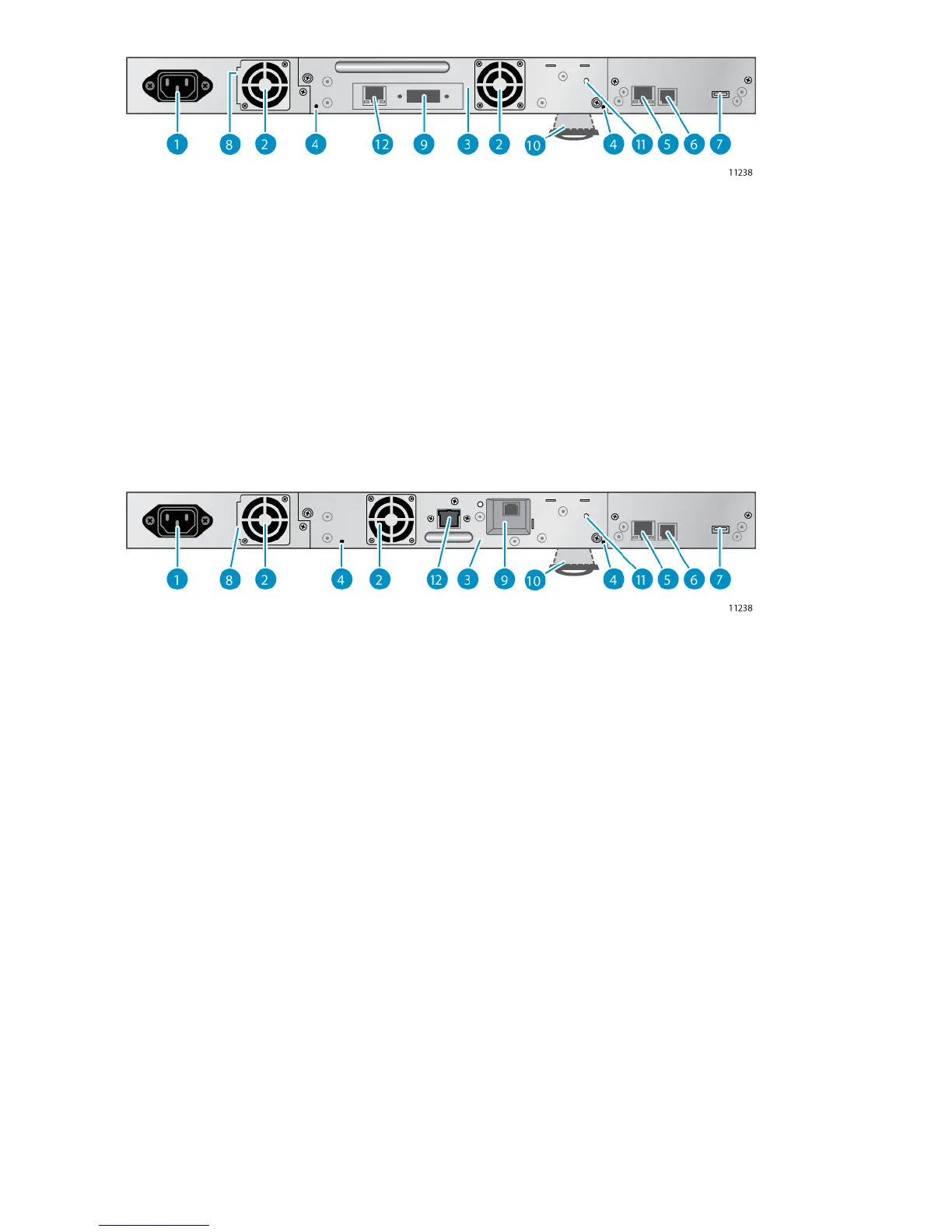
Figure 4 Back panel overview with SAS tape drive
.
2. Fan vent1. Power connector
4. Magazine release hole3. Tape drive
6. Serial port (Factory use only)5. Ethernet port
8. Shipping lock storage location7. USB port
10. Pull-out tab containing the serial number and other
product information.
9. SAS port
12. Tape drive Ethernet port (LTO-5 only)11. Tape drive LED
Figure 5 Back panel overview with FC tape drive
.
2. Fan vent1. Power connector
4. Magazine release hole3. Tape drive
6. Serial port (Factory use only)5. Ethernet port
8. Shipping lock storage location7. USB port
10. Pull-out tab containing the serial number and other
product information.
9. FC port
12. Tape drive Ethernet port (LTO-5 only)11. Tape drive LED
The device requires a 110/220 volt AC power connection.
Tape drive LED
Each tape drive has a green LED, which indicates that the tape drive is powered on (see Figure 6).
Features and overview24