58
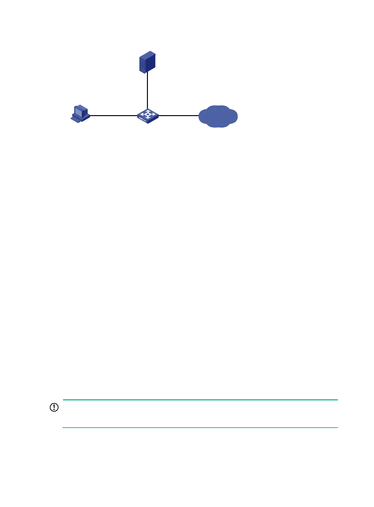
Figure 20 Network diagram
Configuration procedure
Make sure the settings on the switch and the RADIUS server match.
1. Configure the switch:
# Assign VLAN-interface 2 an IP address from the same subnet as the Telnet user.
<Switch> system-view
[Switch] interface vlan-interface 2
[Switch-Vlan-interface2] ip address 192.168.1.70 255.255.255.0
[Switch-Vlan-interface2] quit
# Assign VLAN-interface 3 an IP address from the same subnet as the RADIUS server.
[Switch] interface vlan-interface 3
[Switch-Vlan-interface3] ip address 10.1.1.2 255.255.255.0
[Switch-Vlan-interface3] quit
# Enable Telnet server.
[Switch] telnet server enable
# Enable scheme authentication on the user lines for Telnet users.
[Switch] line vty 0 63
[Switch-line-vty0-63] authentication-mode scheme
[Switch-line-vty0-63] quit
# Create the RADIUS scheme rad and enter RADIUS scheme view.
[Switch] radius scheme rad
# Specify the primary server address 10.1.1.1 and the service port 1812 in the scheme.
[Switch-radius-rad] primary authentication 10.1.1.1 1812
# Set the shared key to expert in the scheme for the switch to authenticate to the server.
[Switch-radius-rad] key authentication simple expert
[Switch-radius-rad] quit
# Specify the scheme rad as the authentication and authorization schemes for the ISP domain
bbb.
Because RADIUS user authorization information is
piggybacked in authentication responses, the
authentication and authorization methods must use the same RADIUS scheme.
[Switch] domain bbb
[Switch-isp-bbb] authentication login radius-scheme rad
[Switch-isp-bbb] authorization login radius-scheme rad
[Switch-isp-bbb] quit
Internet
Switch
Telnet user
192.168.1.58/24
Vlan-int 2
192.168.1.70/24
Vlan-int 3
10.1.1.2/24
RADIUS server
10.1.1.1/24

 Loading...


