______HSD Technological equipment for Automation _____________________________________
5801H0017 Rev. 02 _________________________________________________________ 11/98
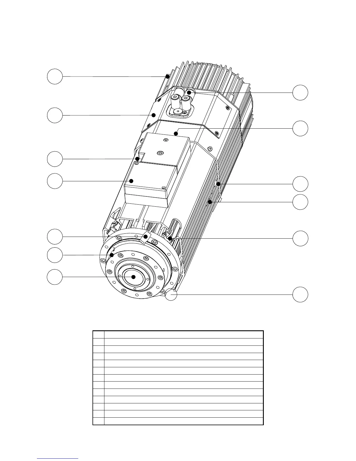
6.3 DESCRIPTION OF THE MAIN PARTS OF THE ELECTRO-SPINDLE
1
2
3
4
5
6
7
8
10
11
12
13
9
Figure 6.3 General view of the electro-spindle
1
Cooling fan
2
Sensor compartment
3
Manual tool holder release button
4
Configurable terminal block (optional)
5
C axis sensor connector (optional C axis)
6
Spindle nose
7
Spindle shaft
8
Compressed air connectors
9
Electrical terminals
10
Exhaust air silencer (one on each side)
11
Threaded service holes (see section 9.3.4 )
12
Temperature sensor for front bearings (optional)
13
“T” slots for anchoring to support