______HSD Technological equipment for Automation _____________________________________
5801H0017 Rev. 02 _________________________________________________________ 77/98
12.2.4.5 The sensor assembly
The sensors are identified by a numbered cable tag. Take care not to mix up the
sensors. This could damage moving parts of the electro-spindle.
The sensors are pre-fitted in calibrated seats to enable them to be quickly fitted to the electro-
spindle at the correct depth.
For this reason always make absolutely sure what sensor you need to replace. The cables of the
sensors installed in the electro-spindle and of those provided as spares are all tagged with a
number ring to facilitate identification (Figure 12.17).
e
1
3
3
22
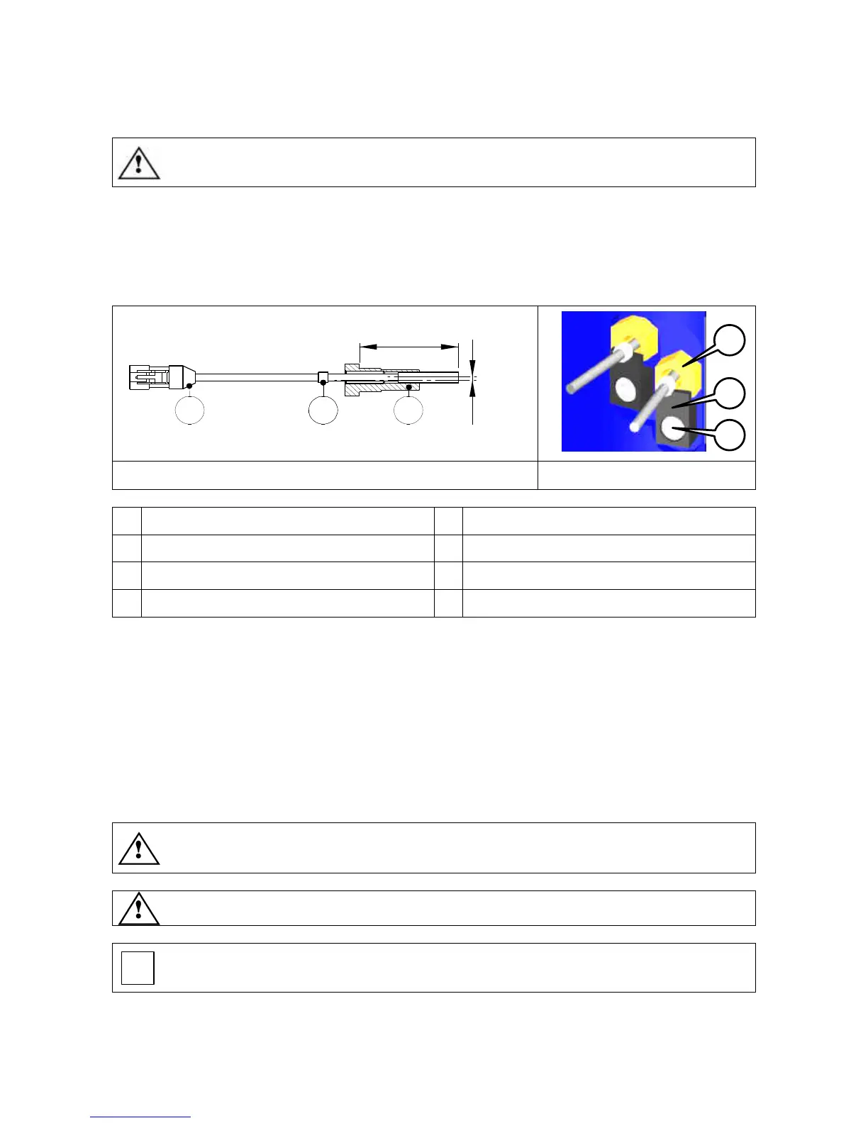
Figure 12.17 Sensor assembly Figure 12.18
1
Electrical connector
e
Adjustment eccentric
2
Cable number ring
4
Sensor
3
Calibrated seat and sensor
5
Sensor fixing bracket
L
Calibrated depth
6
Allen screw
12.2.4.6 Replacing a sensor assembly
Refer to figures Figure 12.17 and Figure 12.18, and proceed as follows to replace the sensors.
1. Remove screw (6) securing the bracket (5) of the sensor to be replaced (4).
2. Pull the faulty sensor out from its housing and disconnect its electrical connector (1).
3. Fit the replacement sensor in the housing and connect the electrical connector.
4. Replace bracket (5) and replace and tighten screw (6). Do not fully tighten yet. Leave it loose
enough to turn the sensor for calibration as described in sections 12.2.4.7 , 12.2.4.8 and
12.2.4.10 .
5. After you have calibrated the sensor, tighten the fixing screw to maintain the calibration setting.
Perform as many tests as possible using all available tool holders to verify the
effectiveness of the new sensor calibration.
Warning: Incorrect sensor calibration can lead to electro-spindle malfunctions.
When reading sections from 12.2.4.7 to 12.2.4.10 on sensor calibration, always
refer to the position numbers in Figure 12.17 and Figure 12.18.