______HSD Technological equipment for Automation _____________________________________
5801H0017 Rev. 02 _________________________________________________________ 79/98
1. Connect compressed air at 6/7 bar (85/100 PSI) to the electro-spindle's cylinder and set the
electro-spindle in a condition of “tool holder ejected (collet open)”.
2. Use a depth callipers as shown in Figure 12.19 to check whether distance (B) from the tip of
the ejector to the nose of the spindle at its maximum is 10.5 ± 0.1 mm. If it is not, do NOT
proceed but contact the HSD Customer Assistance Service.
3. Release the air from the cylinder. The ejector retracts, and (B) returns to its minimum value.
4. Use a pressure regulator to gradually increase pressure in the cylinder and extend the ejector.
5. Stop when distance (B) reaches 10.3 ± 0.1 mm.
6. If necessary, slacken off the fixing screw (6) for sensor S2.
7. Turn the seat (4) of sensor S2 until the sensor gives a “high” signal (24V) with (B) = 10.3 ±
0.1 mm and a “low” signal (0V) with (B) < 10.3 ± 0.1 mm. Hold the sensor seat firmly in this
position.
8. Turn the spindle shaft by hand and check that when (B) = 10.3 ± 0.1 mm the output from S2 is
“high” (24V) and “low” (0V) when (B) < 10.3 ± 0.1 mm through 360° of a complete revolution.
9. Tighten the screw (6) to secure the sensor fixing bracket (5).
10. Perform as many tests as possible using all available tool holders to verify the effectiveness of
the new sensor calibration.
Contact the HSD Customer Assistance Service if distance (B) is not 10.3 ± 0.1 mm
when you feed compressed air at 6/7 bar (85/100 PSI) into the cylinder.
12.2.4.8.3 Procedure for S3
When you have replaced the sensor as instructed in section 12.2.4.6 , proceed as follows to
calibrate it.
1. Check whether the signal output from the sensor corresponds to that illustrated in figure 13.1.
2. If it does not, turn the sensor seat (4) until you obtain the output specified in the table. Hold the
sensor in this position and tighten the fixing screw (6).
12.2.4.8.4 Procedure for S4
When you have replaced the sensor as instructed in section 12.2.4.6 , calibrate it as follows.
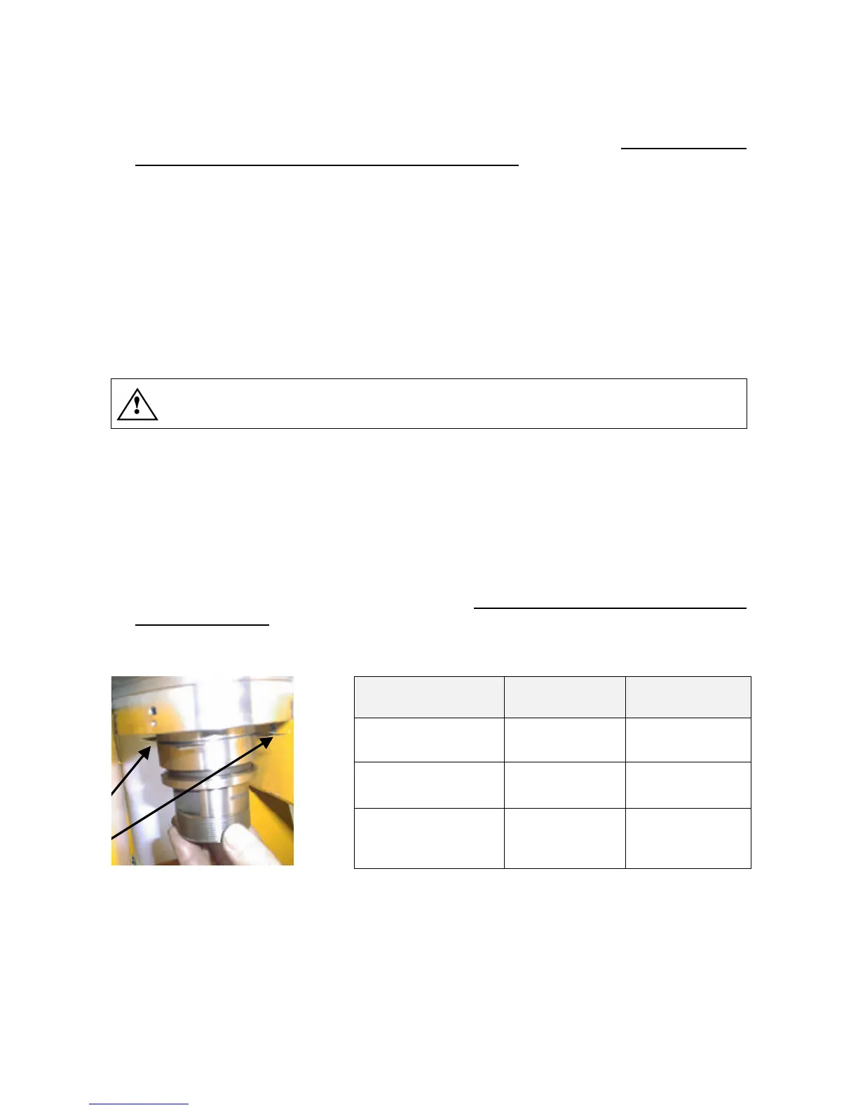
1. Place shims first of thickness 0.12 mm or 0.16 mm between the faces of the tool holder cone
and the spindle shaft as shown in Figure 12.20 in accordance with the table below.
2. Fit and lock the tool holder cone in the spindle shaft and check whether the signal output from
sensor S4 corresponds to that specified in the table below.
CONDITION SHIM IN PLACE OUTPUT S4
Tool holder locked 0.12 mm HIGH (+24V)
Tool holder locked 0.16 mm LOW (0V)
Tool holder ejected
(collet open)
- LOW (0V)
Figure 12.20
3. Turn the spindle shaft by hand and check whether the conditions in the table are fulfilled
throughout the 360° of a complete revolution.
4. If they are not, turn the sensor seat (4) until you obtain the output specified in the table. Hold
the sensor in this position and tighten the fixing screw (6).
5. Perform as many tests as possible using all available tool holders to verify the effectiveness of
the new sensor calibration.