______HSD Technological equipment for Automation _____________________________________
5801H0017 Rev. 02 _________________________________________________________ 91/98
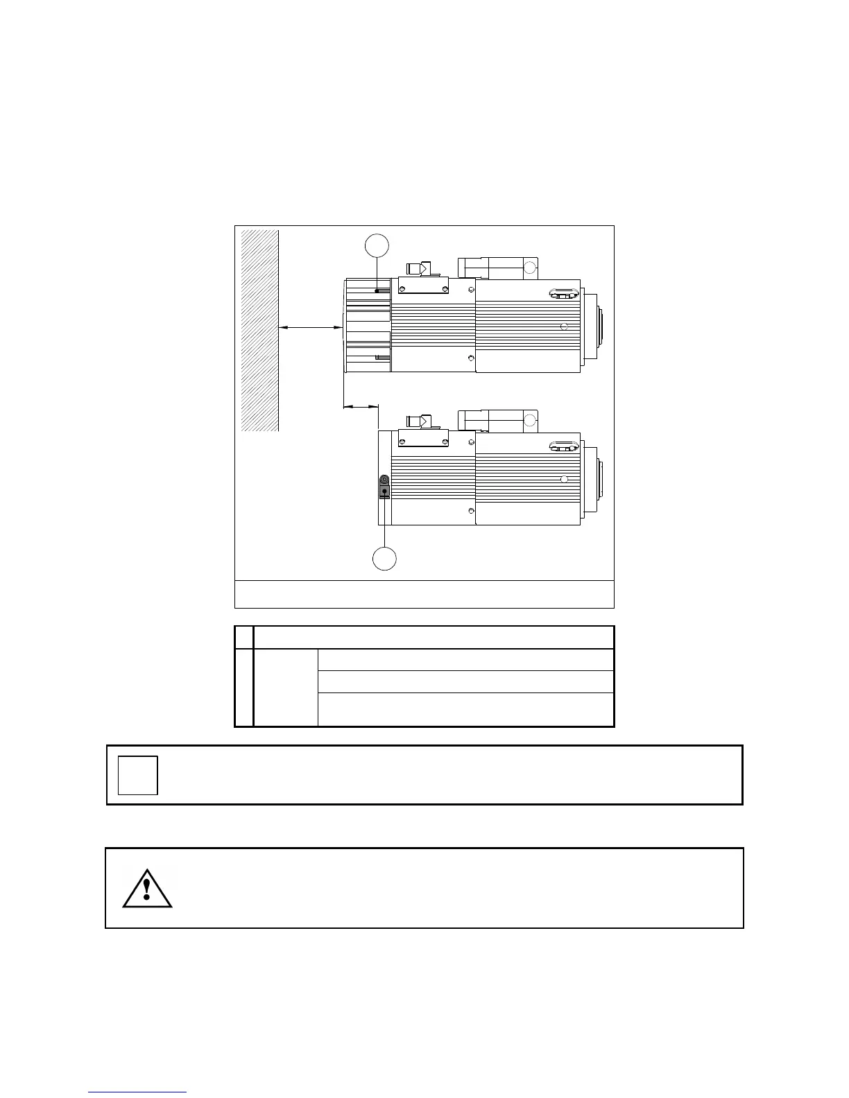
13.4 FORCED AIR COOLING
The electro-spindle can be cooled by compressed air instead of by the cooling fan.
Compressed air is delivered to a distribution flange, pre-fitted by HSD or retro-fitted as a kit.
This cooling solution reduces the overall length of the electro-spindle by 5 cm and dispenses with
the need to maintain a gap (10 cm) behind the fan. Compressed air cooling therefore reduces the
electro-spindle's overall space requirement by 15 cm (Figure 13.5).
A
50
100
B
Figure 13.5
A
Four cooling fan fixing screws
External hose Ø: 8 mm
Pressure: 6 / 7 bar – 85 / 100 PSI
B
Cooling
air inlet
Consumption: 4 cfm referred to 1 Atm, 68°F
(7000 normal litres/hour)
The stated values for air consumption and inlet pressure are for the S1 duty type
described in the tables in chapter § 7. If the unit is used with lighter duty types, the user
can evaluate whether to reduce air consumption by lowering the inlet pressure.
13.4.1 Installing the forced air cooling kit
BEFORE STARTING ANY WORK ON THE ELECTRO-SPINDLE, READ AND
FOLLOW ALL THE SAFETY PRECAUTIONS AND MAINTENANCE SAFETY
WARNINGS.
SEE IN PARTICULAR CHAPTER § 5 AND PAGES 66 AND 71 OF CHAPTER § 12.
1. Remove the fixing screws and pull the fan unit off the electro-spindle (see section 12.2.1 ).
2. Disconnect the cooling fan's electrical connector and fit the bridge connector provided.
3. Fit the air distribution flange in the place of the cooling fan unit and secure it with the four
screws removed from the fan unit.
4. Connect the compressed air supply to the quick-fit union (B) on the air distribution flange.