______HSD Technological equipment for Automation _____________________________________
5801H0017 Rev. 02 _________________________________________________________ 90/98
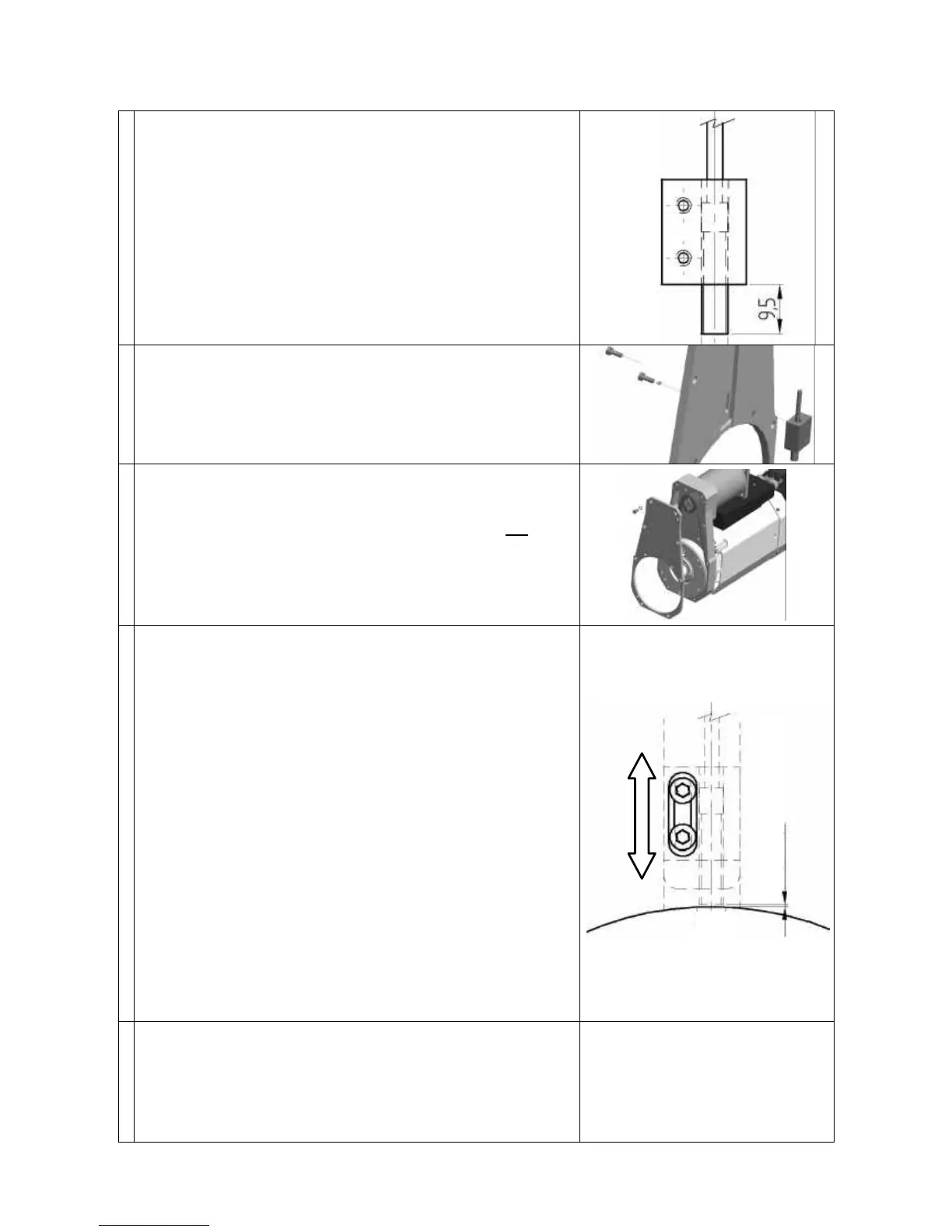
• Apply some Loctite 243 or equivalent medium strength
thread locking compound to the threads of the sensor.
• Screw the sensor into the side of the sensor block with
the largest hole.
• Screw the sensor in until you achieve the protrusion
shown in the figure on the right.
• Wait for the thread locking compound to set in
compliance with the manufacturer's instructions.
• Fit the assembled sensor + sensor block to the cover
(figure on the right), but leave the screws loose enough
for the sensor block to move.
• Apply silicon sealant to the sensor cable hole.
• Check that the C axis unit is still in a position other than
the zero position, i.e. that the drive pin hole is not in the
position shown in Figure 13.4. Turn the C axis unit if
necessary.
• Fit the cover back on the body of the C axis unit. Fit and
tighten all the fixing screws (figure on the right).
• Adjust the sensor read distance using either
“PROCEDURE_A” or “PROCEDURE_B”:
PROCEDURE A
• Place a shim of 0.2 mm between the pulley and the
sensor.
• Push the sensor against the pulley and into firm contact
with the shim.
• Tighten the two sensor block fixing screws.
• Remove the shim.
PROCEDURE B
• Push the sensor against the pulley and check that the
sensor contacts are open.
• Slowly slide the sensor away from the pulley until the
contacts close.
• Slowly slide the sensor towards the pulley again until the
contacts just open.
• Tighten the two sensor block fixing screws.
• Re-connect the electro-spindle's electrical connections.
• Turn the C axis unit, and check that the contacts of
sensor SC remain closed at all positions other than zero
position (see Figure 13.4) when they must open.
• Check sensor functioning at as many axis positions as
practical.