______HSD Technological equipment for Automation _____________________________________
5801H0017 Rev. 02 _________________________________________________________ 76/98
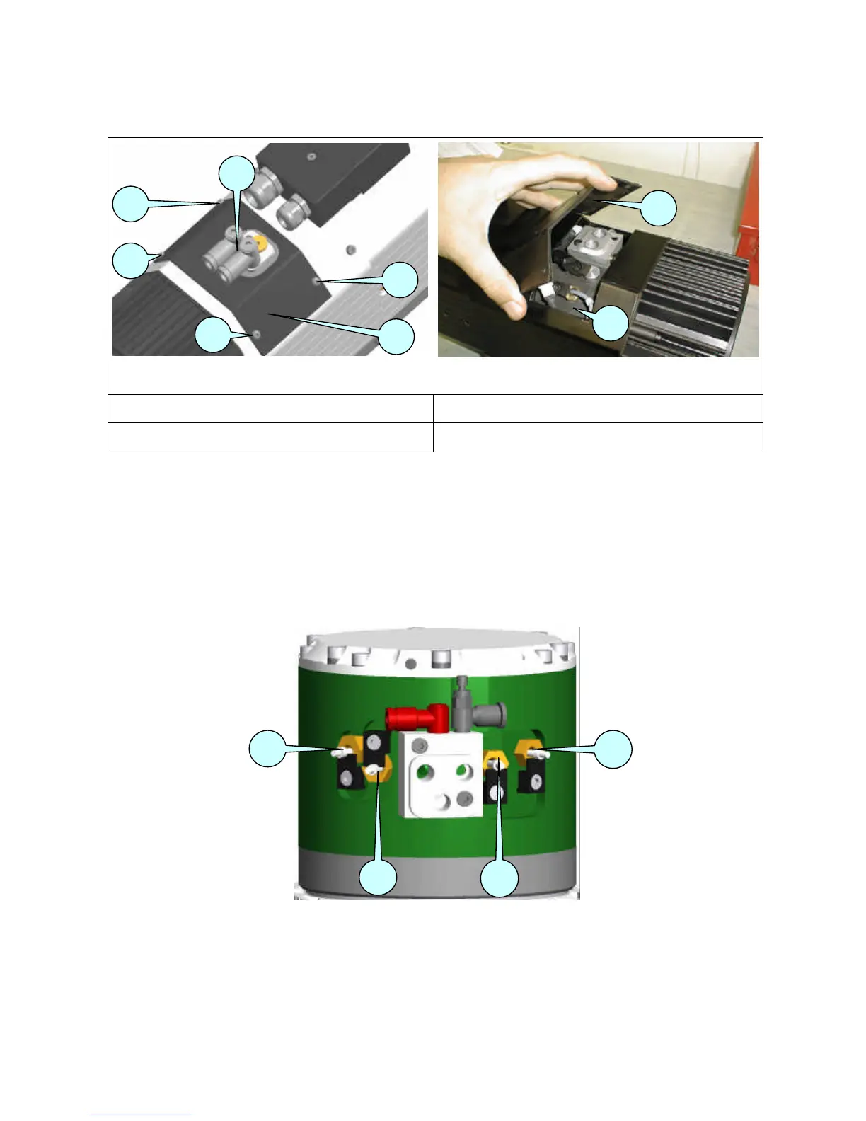
12.2.4.3 Accessing the sensors
Figure 12.14
Figure 12.15
1
PAIR OF QUICK-FIT UNIONS
3
COVER OF SENSOR COMPARTMENT
2
SCREWS
4
SENSOR COMPARTMENT
• Disconnect the air hoses from the quick-fit unions 1, and turn the quick-fit unions to face the
nose of the spindle.
• Remove the screws 2 from the cover 3.
• Remove the cover 3 to access the sensor compartment 4, taking care not to damage the cover
seal.
12.2.4.4 Location of sensors
Figure 12.16 Identification of the sensors