______HSD Technological equipment for Automation _____________________________________
5801H0017 Rev. 02 _________________________________________________________ 47/98
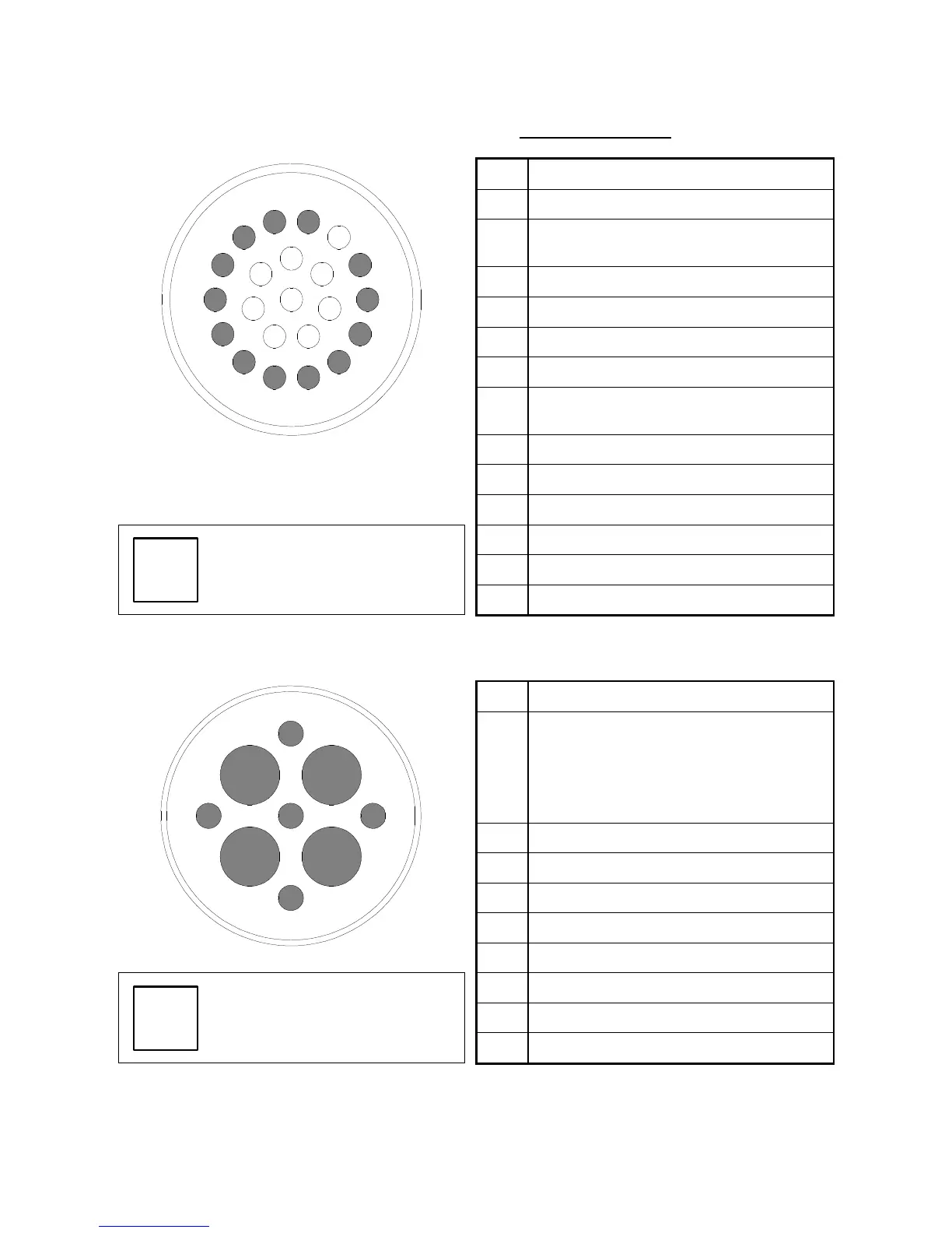
9.6.3 Pin layout of fixed signals connector - HSK F63 version
PIN DESCRIPTION
1
Sensor S2 (tool ejected) output
2
Sensor series S1 + S4 (tool locked)
output
3
Sensor S3 (shaft stopped) output
4
+24V DC power to S1, S2, S3
5
+24V DC power to push-button lamp
6
0V power to S1, S2, S3, S4
7
+24V DC power to push-button and C
axis zeroing sensor (SC sensor)
8
Push-button output
7
14
1
2
13
15
12
3
16
8
21
22
20
4
17
11
18
5
19
10
6
9
9
Temperature sensor for front bearings
10
Temperature sensor for front bearings
11
0V power to push-button, lamp, and SC
12
C axis zeroing sensor output (SC sensor)
Use AWG22 wires.
14
For maintenance
9.6.4 Pin layout of fixed power connector
PIN DESCRIPTION
1
Thermal switch: normally closed bi-
metallic switch to be connected in series
to machine safety stop system.
230V AC MAX; 48V DC MAX; 1.6A MAX
2
W PE common to pin 7
3
230V AC 50/60 Hz cooling fan
4
U Motor phase
5
Thermal switch (see pin 1)
2
5
3
4
6
1
8
9
7
6
V Motor phase
7
W PE common to pin 2
8
W Motor phase