______HSD Technological equipment for Automation _____________________________________
5801H0017 Rev. 02 _________________________________________________________ 44/98
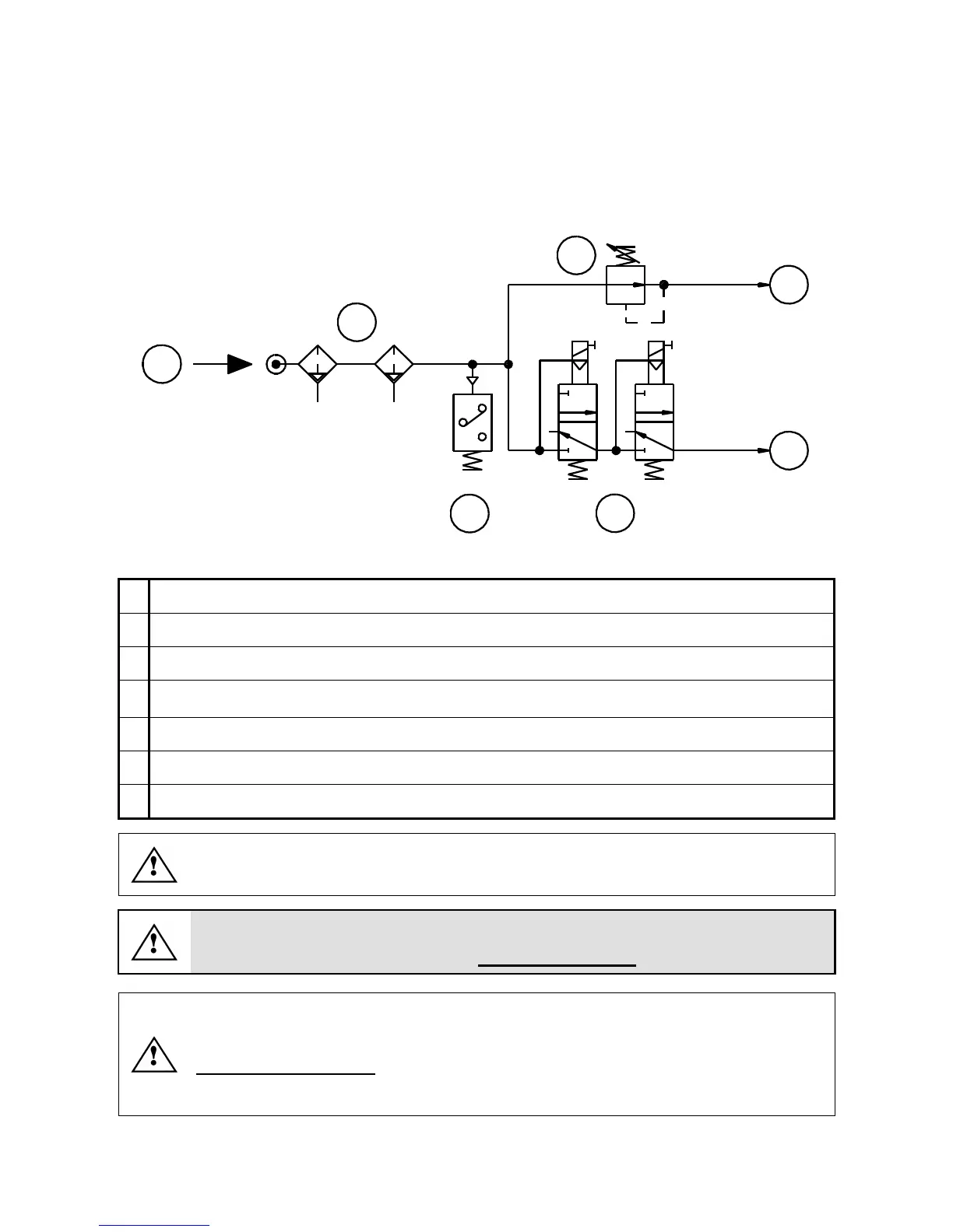
9.4.2 Functional diagram of electro-spindle compressed air connections
Figure 9.6 shows typical compressed air system connections, to be prepared by the customer. The
use of two solenoid valves connected in series reduces the risk of system malfunctions. Though it
is very rare for this type of fault to occur, it can have very serious consequences if it does.
Redundancy is therefore recommended.
5 µ
0,1 µ
1
2
3
5
6 7
4 bar (58 PSI)
4
7 bar (100 PSI)
7 bar (100 PSI)
Figure 9.6 Typical compressed air connection diagram
1
Cone cleaning and internal pressurization air inlet (see also n°1 in Figure 9.5)
2
Tool holder release air inlet (see also n°2 in Figure 9.5)
3
Factory air supply inlet
4
Compressed air filtration/drying group with automatic condensate drain: first stage 5µ and
second stage 0.1µ
5
4 bar (58 PSI) pressure regulator
6
Pressure switch
7
Pair of 3 way, mono-stable solenoid valves
Use 2 separate circuits to connect the solenoid valves (pos. 7 in Figure 9.6) to the
numeric control unit or manual control system.
IMPORTANT:
The air supply to the compressed air circuit
must be dry and filtered
When the machine is powered on, pressurized air must be delivered even when the
electro-spindle is stopped, to prevent dust and dirt from the machining area from
entering the electro-spindle (see section7.7.3 ).
With the spindle stopped, make sure that there is uniform flow of air around the spindle
shaft (pressurization air). If there is not, check the compressed air circuit and
connections.