______HSD Technological equipment for Automation _____________________________________
5801H0017 Rev. 02 _________________________________________________________ 48/98
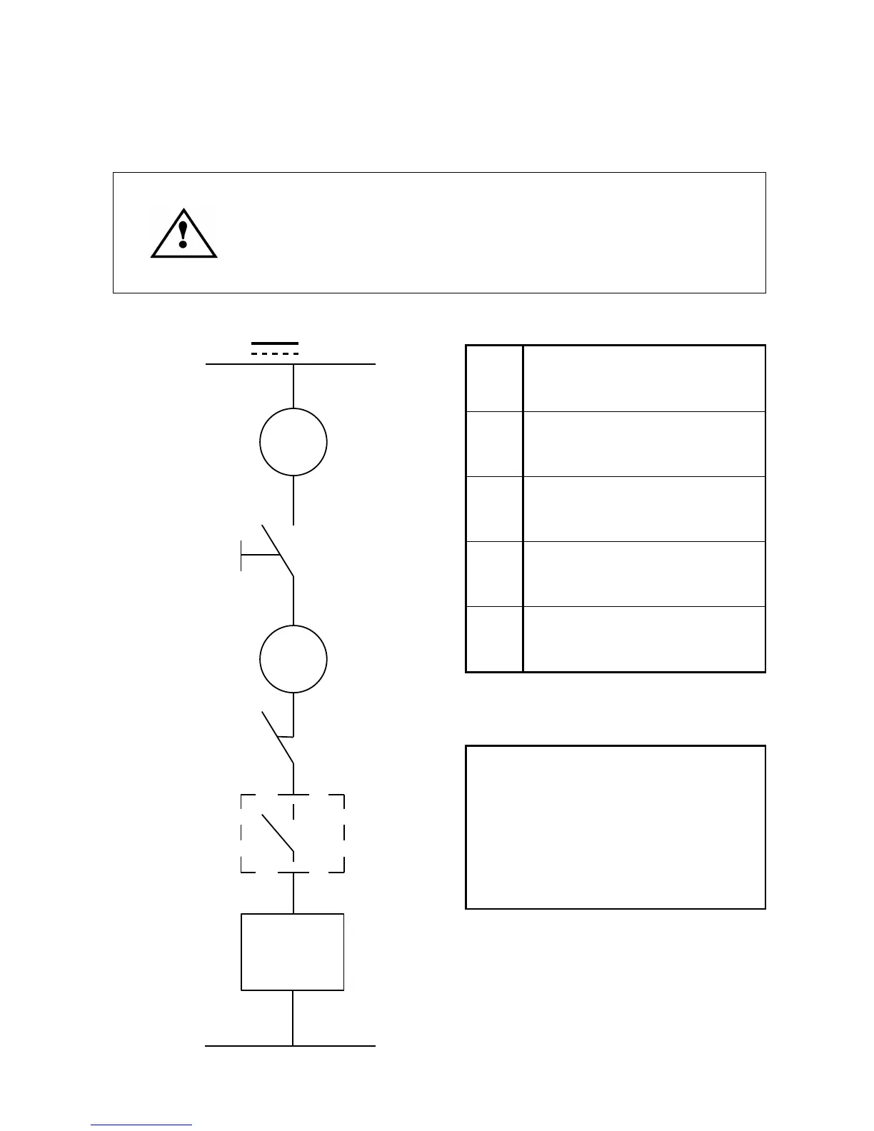
9.6.5 Tool holder release system electrical wiring diagram for electro-spindles
not controlled by CNC
• The control system must disable the tool release push-button
signal while the spindle is rotating.
• The push-button must only be enabled when the spindle is
completely stationary.
• Only use the push-button to lock/release tools on manually
controlled machines.
7 - 8
Pins 7 and 8 of the signals
connector
B
Tool release button
(See section 7.7.5 for technical
specifications.)
P
Pressure switch to prevent tool
release in case of insufficient air
pressure
C
Safety check (spindle stopped
check device)
E
Tool release solenoid valves (See
pos. 7 in Figure 9.6 and the
warnings for it.)
• When button “B” on the electro-
spindle is pressed, the coils of
solenoids “E” (not supplied) are
energized and the tool holder is
released.
• Press button “B” to release the tool
holder.
24V
7
B
8
P
C
0 V
E