______HSD Technological equipment for Automation _____________________________________
5801H0017 Rev. 02 _________________________________________________________ 50/98
§ 10 GENERAL CHECKS AFTER INSTALLATION AND DURING
START-UP
10.1 CHECKING THE ELECTRO-SPINDLE BEFORE START-UP
Positioning
• There must be at least 100 mm of free space behind the cooling fan cover.
Compressed air connections
• The internal pressurization and cone cleaning air hose must have an external
diameter of 8 mm, and must deliver dry, filtered air at a pressure of 4 bar (58 psi).
• The tool change air hose must have an external diameter of 8 mm, and must
deliver dry, filtered air at a pressure of 7 bar (100 psi).
• (For connection details see the labels on the unit itself and see also section 9.4
above).
THE TOOL RELEASE CYLINDER IS
SINGLE ACTING.
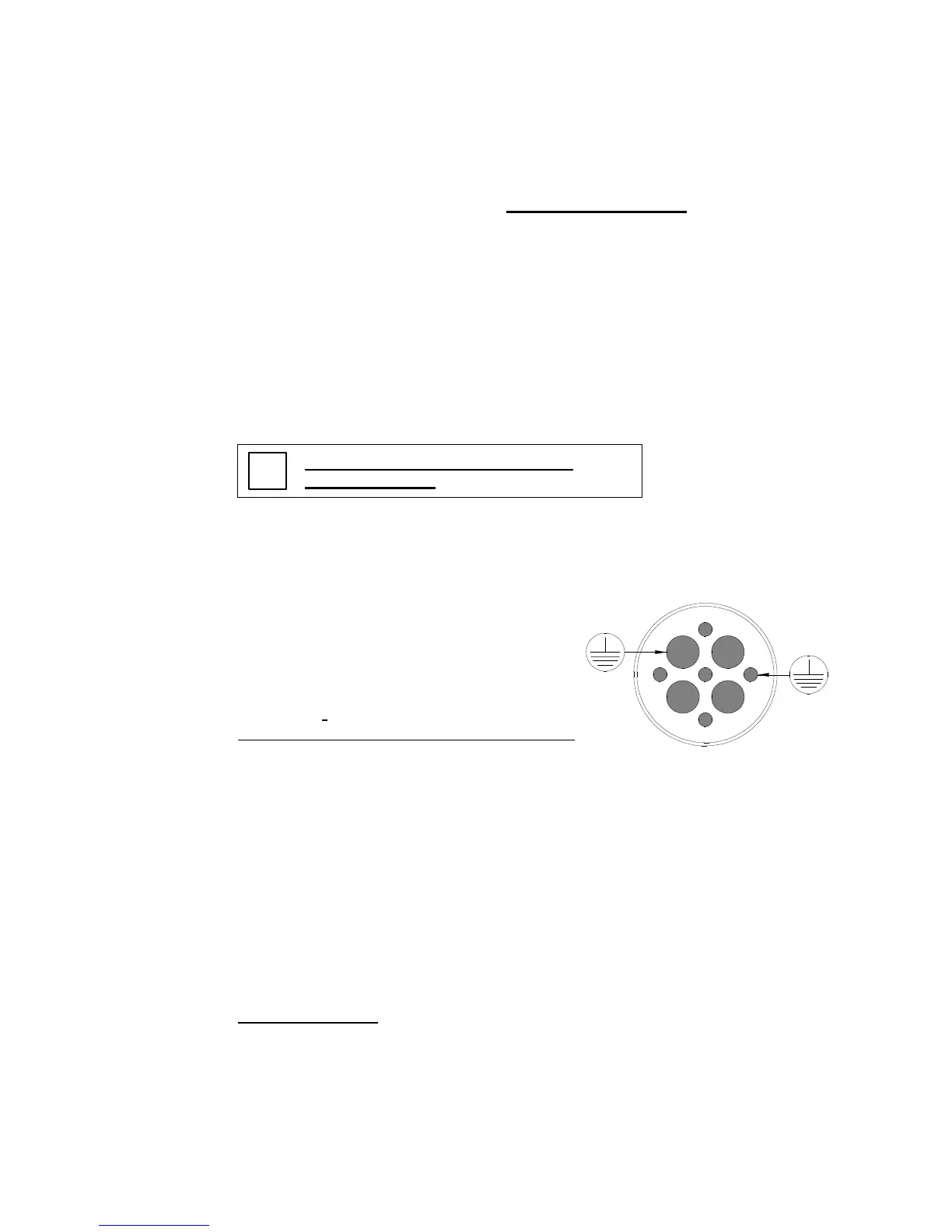
Electrical connections
• The ground wire of the electro-spindle and
cooling fan must be connected to the ground
(pins 2 and 7 of the power connector in the
figure on the right).
• The motor's thermal switch (NC switch) must
be connected in series with the machine's
safety stop system (pins 1 and 5 of the power
connector in the figure on the right and section
9.6.4 above).
• 2 pole 220V - 380V configurable motors only:
The connections in the terminal block (380 V
star or 220 V delta) must match the electro-
spindle power. (See section 9.6.6 and § 7.)
2
5
3
4
6
1
8
9
7
Inverter programming
• The maximum power voltage setting must match the value on the electro-spindle's
data label.
• The minimum frequency value at which maximum voltage is delivered (rated
frequency, also referred to as knee or bend frequency) must match the value on
the electro-spindle's data label.
• The maximum frequency value must match the value on the electro-spindle's data
label.
• The maximum continuous current value must match the value on the electro-
spindle's data label.
• Contact HSD S.p.a. if you wish to check other inverter parameters.