______HSD Technological equipment for Automation _____________________________________
5801H0017 Rev. 02 _________________________________________________________ 75/98
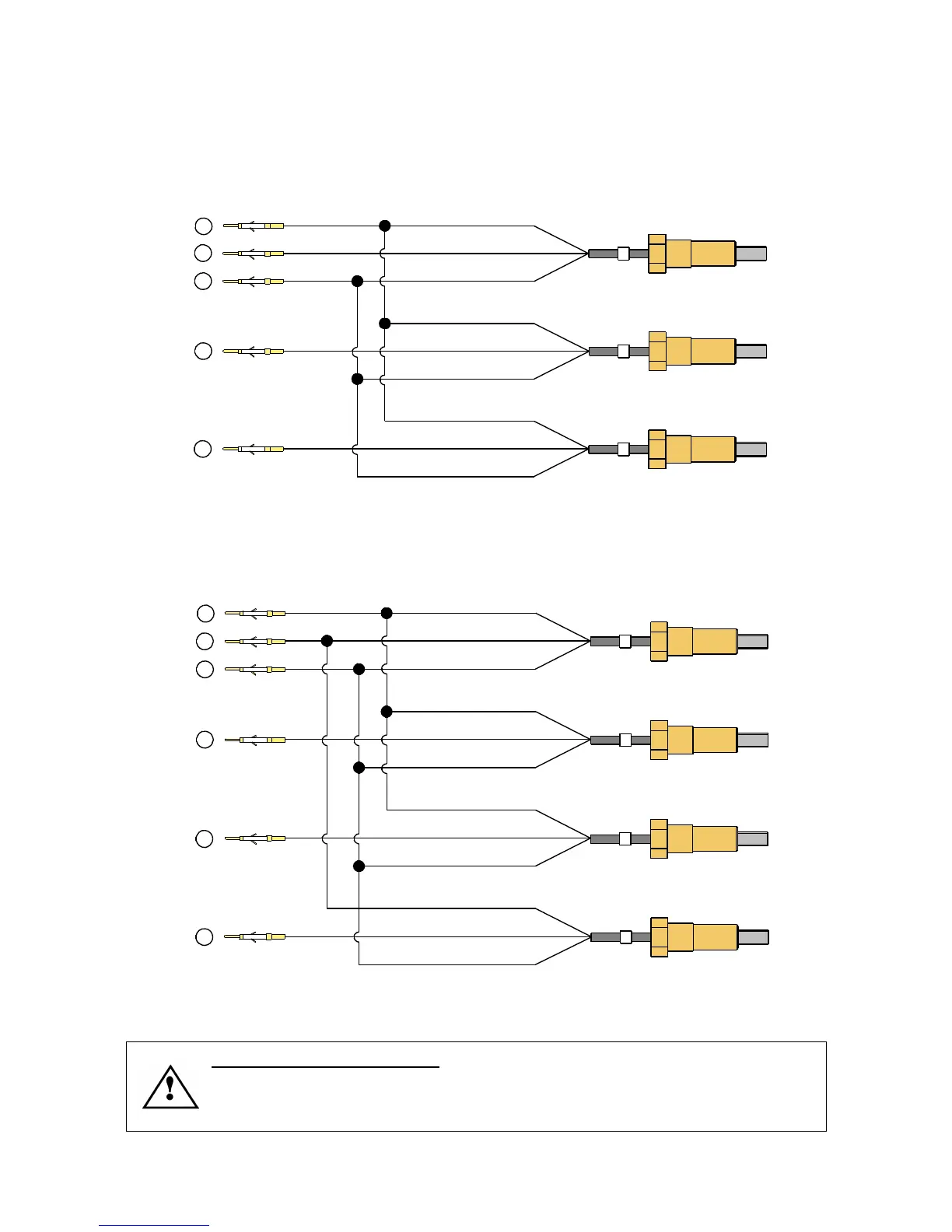
12.2.4 Replacing sensors S1, S2, S3 and S4
12.2.4.1 Wiring of sensors in ISO 30 versions
PIN 4
PIN 6
S2
PIN 1
S3
PIN 3
PIN 2
3
1
2
Figure 12.12 Connection of sensors in ISO 30 electro-spindles to the pins of the signals connector (see
section 9.6.2 )
12.2.4.2 Wiring of sensors in HSK versions
4
1
2
PIN 4
PIN 6
PIN 1
PIN 2
14
S3
3
PIN 3
PIN
Figure 12.13 Connection of sensors in HSK electro-spindles to the pins of the signals connector (see section
9.6.3 )
NOTE FOR HSK VERSIONS: The output to pin “14” must not be used for
machine control purposes, but only to identify which sensor in the <S1+S4> set is
faulty in case of malfunction, and to calibrate sensor S1 as instructed in sections
12.2.4.8 and 12.2.4.10 .