______HSD Technological equipment for Automation _____________________________________
5801H0017 Rev. 02 _________________________________________________________ 63/98
11.6 SENSOR FUNCTIONING
Note: The optional sensors (the “spindle shaft stopped” sensor S3
and the “front bearing temperature sensor”) are optionally
installed in ISO 30 and HSK F63 versions. They are both
described in detail in chapter § 13, where sensor “SC” for the
optional “C” axis is also described.
This section only describes the sensors present in the basic
configuration.
The technical specifications of the sensors described here are
given in section 7.7.4 .
Sensor output is delivered to the “signals connector” described
in sections 9.6.2 (ISO 30) and 9.6.3 (HSK F63).
11.6.1 ISO 30 versions
ISO 30 versions are fitted with two electro-spindle sensors. Sensors S1 and S2 perform the
functions described below.
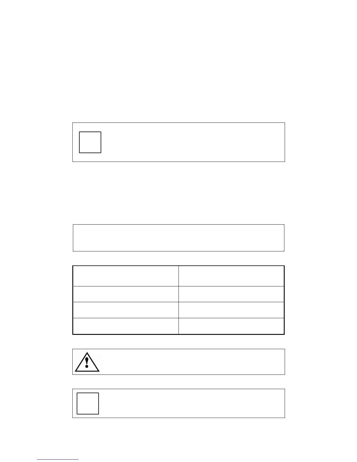
S1
Detects correct locking of the tool holder. It is used to
provide the NC with a safety signal permitting spindle
rotation.
CONDITION
OUTPUT S1
Tool holder locked +24 V
No tool holder 0 V
Tool holder ejected
(collet open)
0 V
Always monitor S1 during electro-spindle rotation and stop
rotation if S1 drops to 0 Volt.
Ignore S1 from the moment the tool eject command is
given until the next tool locking command is given.