______HSD Technological equipment for Automation _____________________________________
5801H0017 Rev. 02 _________________________________________________________ 46/98
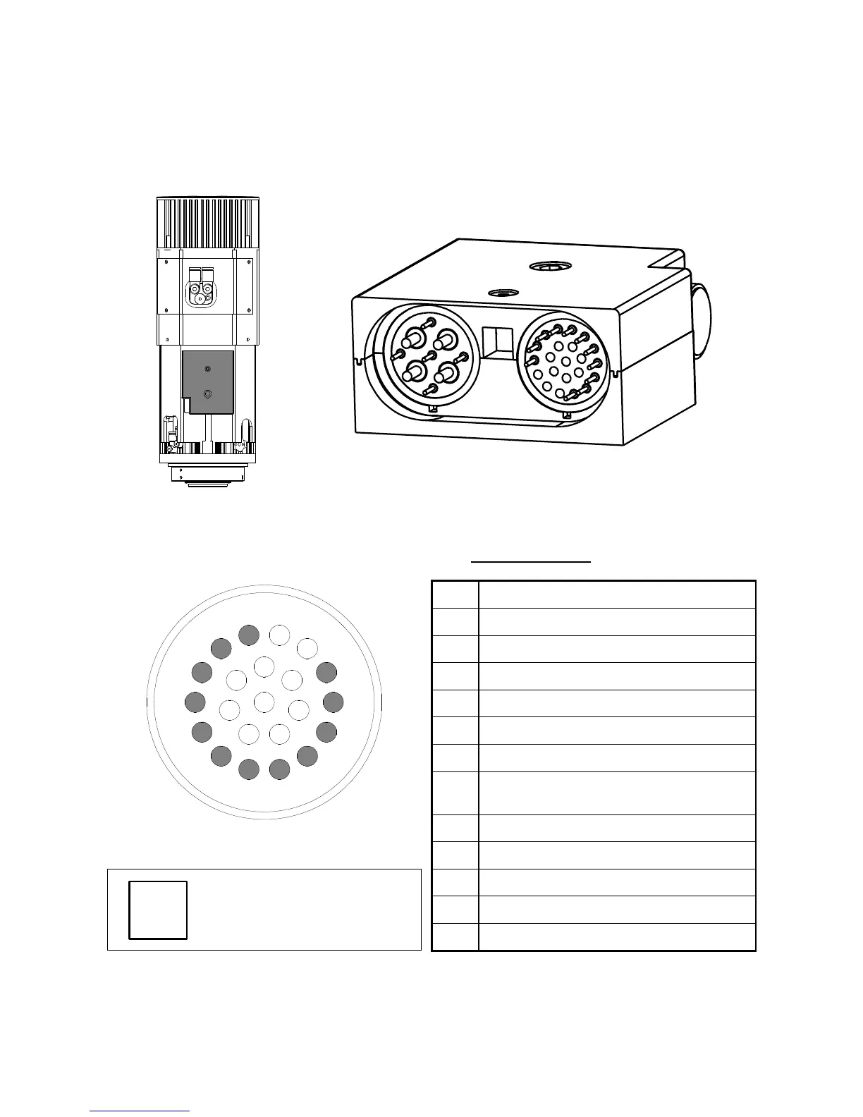
9.6 ELECTRICAL CONNECTIONS
9.6.1 Connectors
The electro-spindle is fitted with two connectors, one for power and the other for signals.
Figure 9.7 Location of electrical connectors
9.6.2 Pin layout of fixed signals connector - ISO 30 version
PIN DESCRIPTION
1
Sensor S2 (tool ejected) output
2
Sensor S1 (tool locked) output
3
Sensor S3 (shaft stopped) output
4
+24V DC power to S1, S2, S3
5
+24V DC power to push-button lamp
6
0V power to S1, S2, S3
7
+24V DC power to push-button and
C axis zeroing sensor (SC sensor)
8
Push-button output
7
14
1
2
13
15
12
3
16
8
21
22
20
4
17
11
18
5
19
10
6
9
9
Temperature sensor for front bearings
10
Temperature sensor for front bearings
11
0V power to push-button, lamp, and SC