______HSD Technological equipment for Automation _____________________________________
5801H0017 Rev. 02 _________________________________________________________ 65/98
S2
Important during tool changes. Detects ejection of the
tool holder, permitting the next phase in the tool change
cycle to take place.
CONDITION
OUTPUT S2
Tool holder locked 0 V
No tool holder 0 V
Tool holder ejected
(collet open)
+24 V
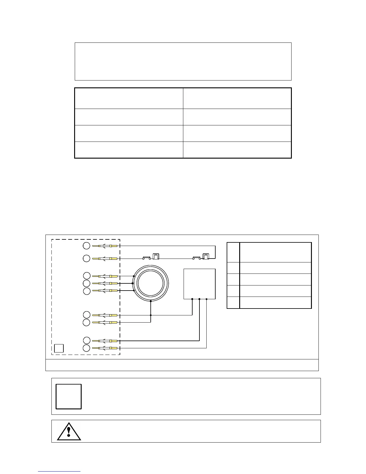
11.7 THERMAL SWITCH
The electro-spindle is protected by two normally closed bi-metallic switches wired in series. These
protect the electro-spindle motor and cooling fan motor respectively.
They must be connected in series with the machine's safety stop system or inverter safety stop
system (see section 9.6.4 ).
The switches open if temperature reaches a potentially damaging level, tripping the machine's
safety stop system and stopping machining. They close again when temperature drops to normal
operating levels.
C
Power connector
(see section 9.6.4 )
S
Bi-metallic switches
M
Electro-spindle motor
F
Cooling fan
PE
Electrical protection W
C
3 ~
PIN 1
PE
F
M
S
PIN 8
PIN 9
PIN 3
PIN 6
PIN 4
PIN 7
PIN 2
PIN 5
S
Figure 11.3 Bi-metallic switch and motor wiring
The fan's thermal switch only detects fan motor overheating. It cannot detect that
the fan is prevented from turning, unless this causes overheating. For this
reason, check the condition of the fan regularly.
The fan must remain on at all times when the machine is active even if the
electro-spindle is not operating.