______HSD Technological equipment for Automation _____________________________________
5801H0017 Rev. 02 _________________________________________________________ 41/98
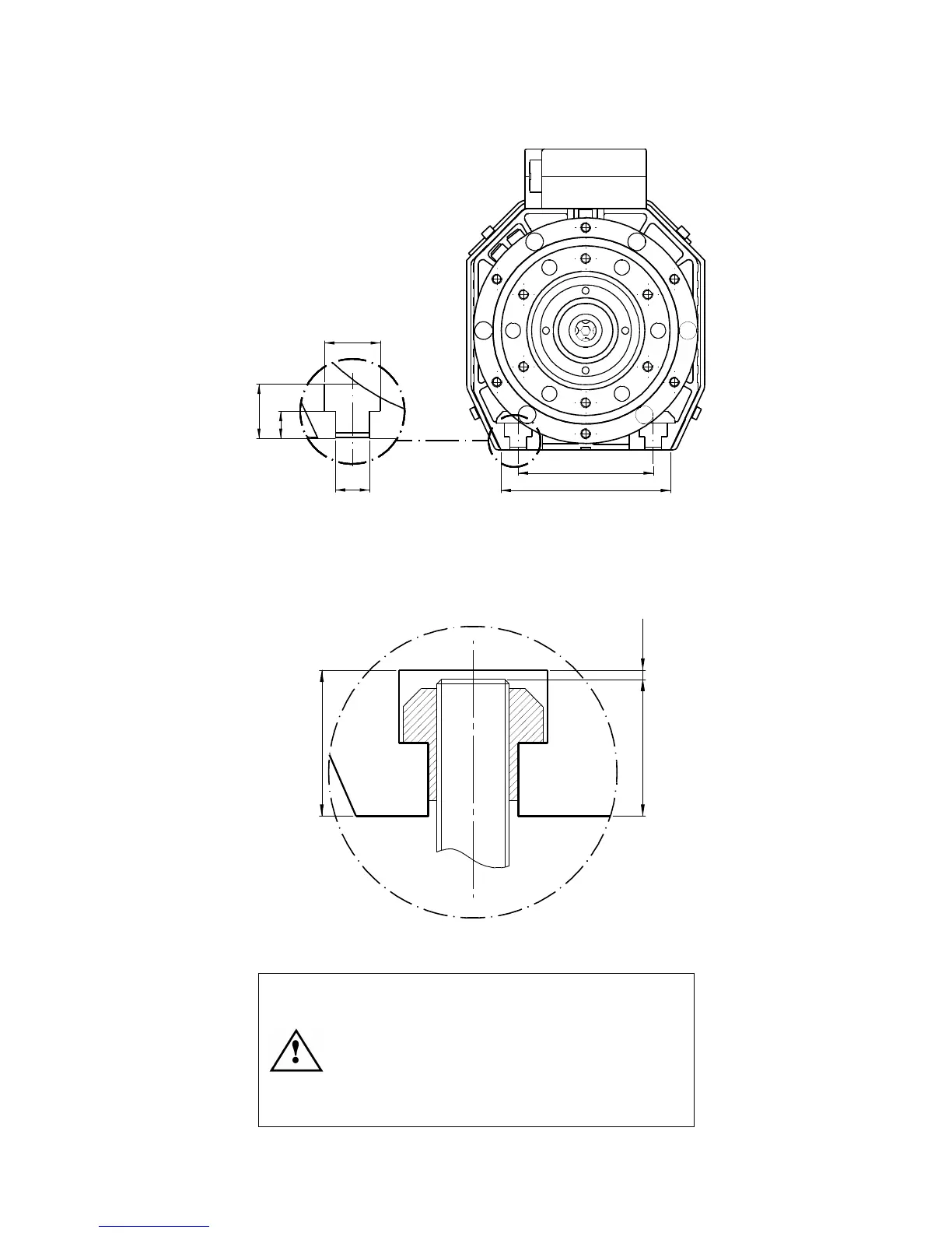
9.3.3 Mechanical fixing of the electro-spindle
80
100,5
10
8
16,5
Figure 9.2 T slots for anchoring the electro-spindle
Fix the electro-spindle to the carriage or spindle mounting using M8 bolts and nuts fitted in the T
slots and tightened to a torque of 20 Nm. Maximum permitted protrusion of the fixing bolts is 15
mm, as shown in Figure 9.3. Greater protrusion can deform the electro-spindle body and lead to
incorrect fixing, reduced machining precision and reduced machining safety.
(16)
15 MAX 1 MIN
Figure 9.3 Maximum permitted protrusion of bolts in T slots
Maximum protrusion of bolt: 15 mm.
Leave a clearance of at least 1 mm.
Excessive protrusion can deform the
electro-spindle body and reduce machining
precision and safety.