______HSD Technological equipment for Automation _____________________________________
5801H0017 Rev. 02 _________________________________________________________ 86/98
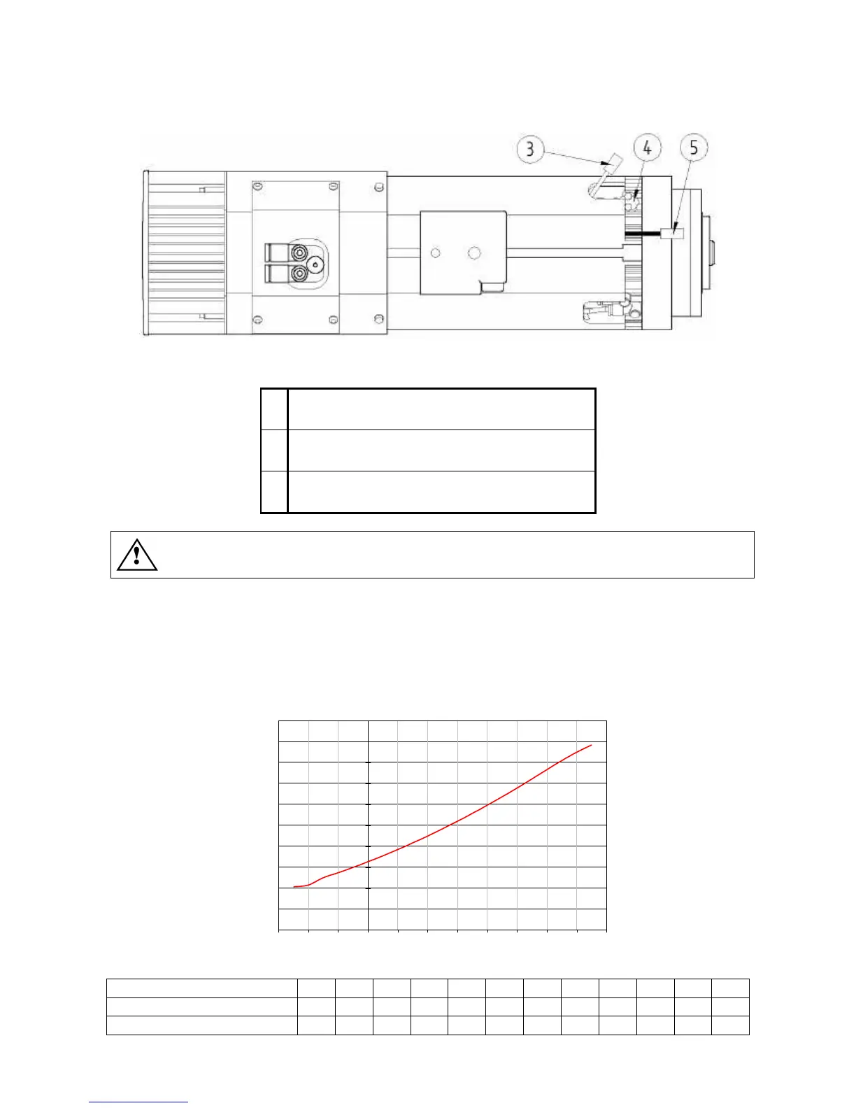
13.2.1 Installing the bearing temperature sensor
Figure 13.3
3
Electrical connector for bearing temperature
sensor (in shrink wrapped protective sheath)
4
Sensor hole with protective cover secured by
two screws
5
Connector for sensor SC of the gear driven C
axis (optional C axis)
Take care not to mix up connector 3 with connector 5.
• Remove the cover fixing screws and remove the cover from the temperature sensor hole 4.
• Fit the seat 1 in the hole 4.
• Fix the sensor in place with the two screws previously removed from the cover.
• Remove the shrink wrapped sheath from connector 3.
• Connect connector 2 to connector 3.
13.2.2 Characteristic curve of the temperature sensor referred to 1 mA
Temperature in °C
Resistance +/- 2% (Ohm)
815 886 961 1000 1040 1122 1208 1299 1392 1490 1591 1696
Temperature +/- 5% (°C) 0 10 20 25 30 40 50 60 70 80 90 100
Temperature +/- 5% (°F) 32 50 68 77 86 104 122 140 158 176 194 212