______HSD Technological equipment for Automation _____________________________________
5801H0017 Rev. 02 _________________________________________________________ 85/98
§ 13 ACCESSORIES AND OPTIONS
BEFORE STARTING ANY WORK ON THE ELECTRO-SPINDLE, READ AND
FOLLOW ALL THE SAFETY PRECAUTIONS AND MAINTENANCE SAFETY
WARNINGS.
SEE IN PARTICULAR CHAPTER § 5 AND PAGES 66 AND 71 OF CHAPTER § 12.
On request, the electro-spindle can be fitted with the following accessories and options:
1. "Spindle shaft stopped" sensor S3 (See section 13.1 )
2. Bearing temperature sensor (See section 13.2 )
3. Belt driven C axis (See section 13.3 )
4. Gear driven C axis (See section 13.3 )
5. Forced air cooling (See section 13.4 )
13.1 "SPINDLE SHAFT STOPPED" SENSOR S3
The “SPINDLE SHAFT STOPPED” sensor outputs two “ON” and two “OFF” pulses per shaft
revolution. It remains permanently “ON” at high speeds.
+ 24 V
0 V
0
giri
rev
1
Figure 13.1 Output from sensor S3
See section 7.7.4 for the sensor's electrical specifications.
See section 12.2.4 to install and calibrate the sensor. Make sure that output is as specified in
Figure 13.1.
Ignore the output of S3 during tool changes.
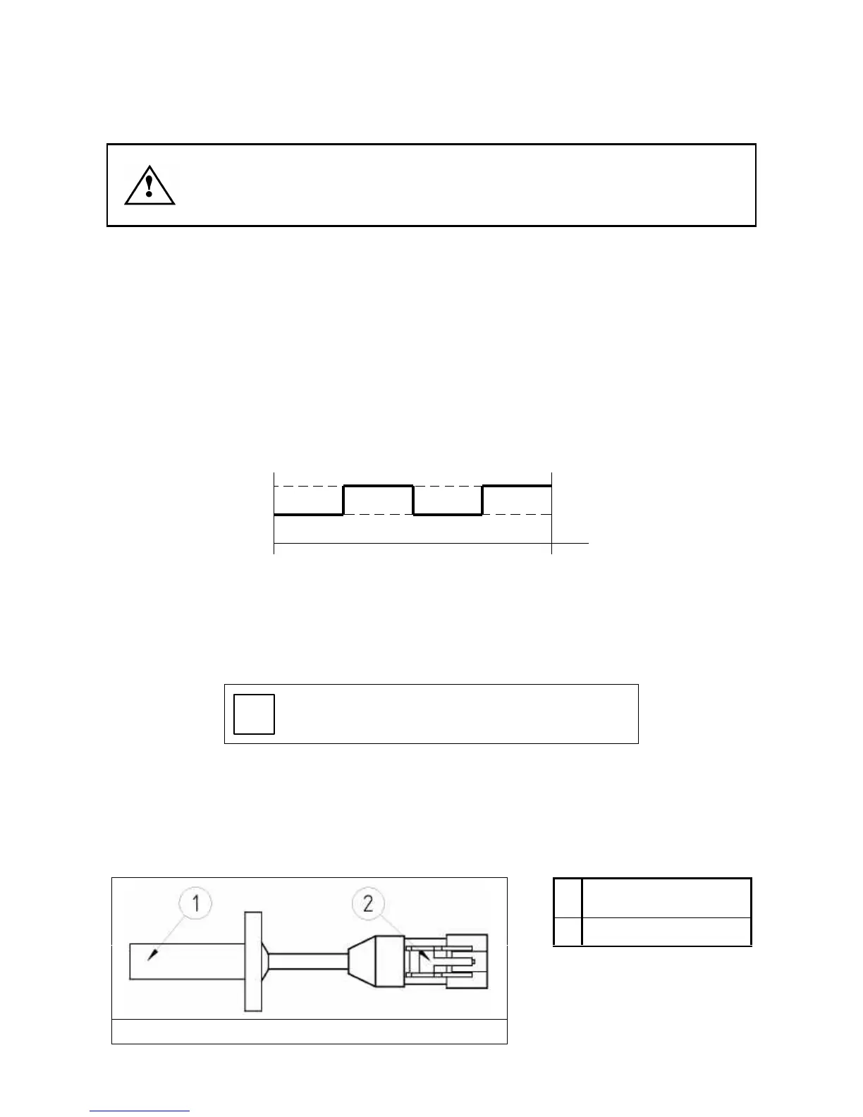
13.2 BEARING TEMPERATURE SENSOR
A temperature sensor (PT 1000 type) can be fitted to the electro-spindle to detect high bearing
temperatures.
The sensor can be connected to any numeric controller capable of interfacing with a temperature
sensitive resistance (analog input).
1
Seat for sensor hole
(Pos. 4 in Figure 13.3)
2
Electrical connector
Figure 13.2