______HSD Technological equipment for Automation _____________________________________
5801H0017 Rev. 02 _________________________________________________________ 89/98
13.3.4 Replacing and calibrating the SC sensor in belt drive versions
BEFORE STARTING ANY WORK ON THE ELECTRO-SPINDLE, READ AND
FOLLOW ALL THE SAFETY PRECAUTIONS AND MAINTENANCE SAFETY
WARNINGS.
SEE IN PARTICULAR CHAPTER § 5 AND PAGES 66 AND 71 OF CHAPTER § 12.
• Turn the C axis to any position other than the zero
reference position, i.e. to any position other than that
shown in Figure 13.4.
• Disconnect the electro-spindle from the electrical supply.
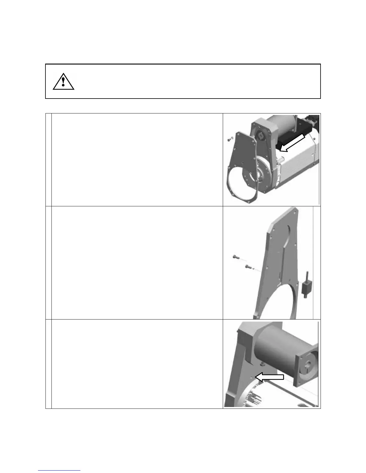
• Remove the eight fixing screws and remove the cover
from the body of the C axis unit (see figure on the right).
• Disconnect the sensor's electrical connector, which is
located in the point shown by the arrow in the figure on
the right (see also position 5 of Figure 6.3 in chapter § 6).
• Cut the cable of the faulty sensor to facilitate removal.
• Remove the two screws fixing the sensor block to the
cover (figure on the right).
• Insert the new sensor in the hole shown by the arrow in
the figure on the right.