FusionModule2000 Smart Modular Data Center
Product Description
5 Power Supply and Distribution System
Copyright © Huawei Technologies Co., Ltd.
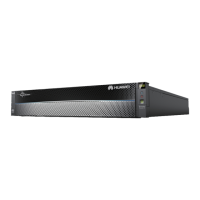
Figure 5-43 Monitoring interface card
The maximum voltage and current of ports DO_1 to DO_4 are 30 V DC, 1 A or 60 V DC, 0.5 A
respectively.
Table 5-24 Ports on the monitoring interface card
DO_1, DO_2, DO_3, and DO_4 indicate alarm
outputs. Their default values are Critical alarm,
Minor alarm, Bypass mode, and Battery mode,
respectively.
It can be set to Disable, Critical alarm, Minor
alarm, Bypass mode, Battery mode, Low batt.
volt., Low battery SOC, Abnormal mains, Sys
maint breaker enable, Sys outp breaker
enable, Maint. breaker closed, No power
supplied, Mains supplies power, ECO mode,
Battery test, and Batt. Volt. Below Thres..
Configure power segment settings based on
backup time.
Provides FE, RS485, I2C, and CAN signals.
Battery
temperature sensor
port
Connects to an indoor battery temperature sensor.
Southbound
communications
port 1
Supported protocol: Modbus-RTU.
Connects to a southbound device.
Southbound
communications
port 2
Supported protocol: Modbus-RTU.
In use.
Supported protocols: Modbus-TCP, HTTPS, and
SNMP (reserved).
Connects to a Huawei northbound device.