ecification
[2] Read position table data
In [1], the target position, positioning band and speed were written one by one to the position table under No. 10
corresponding to positioner mode axis (0). Next, an example of reading data from this position table is explained.
Query Send Procedure
[1] Send a position table data read query
(Write command data to the request command area)
[2] Send a response command area read query.
When a position table data read command is received, the gateway unit will output response data to the response
command area.
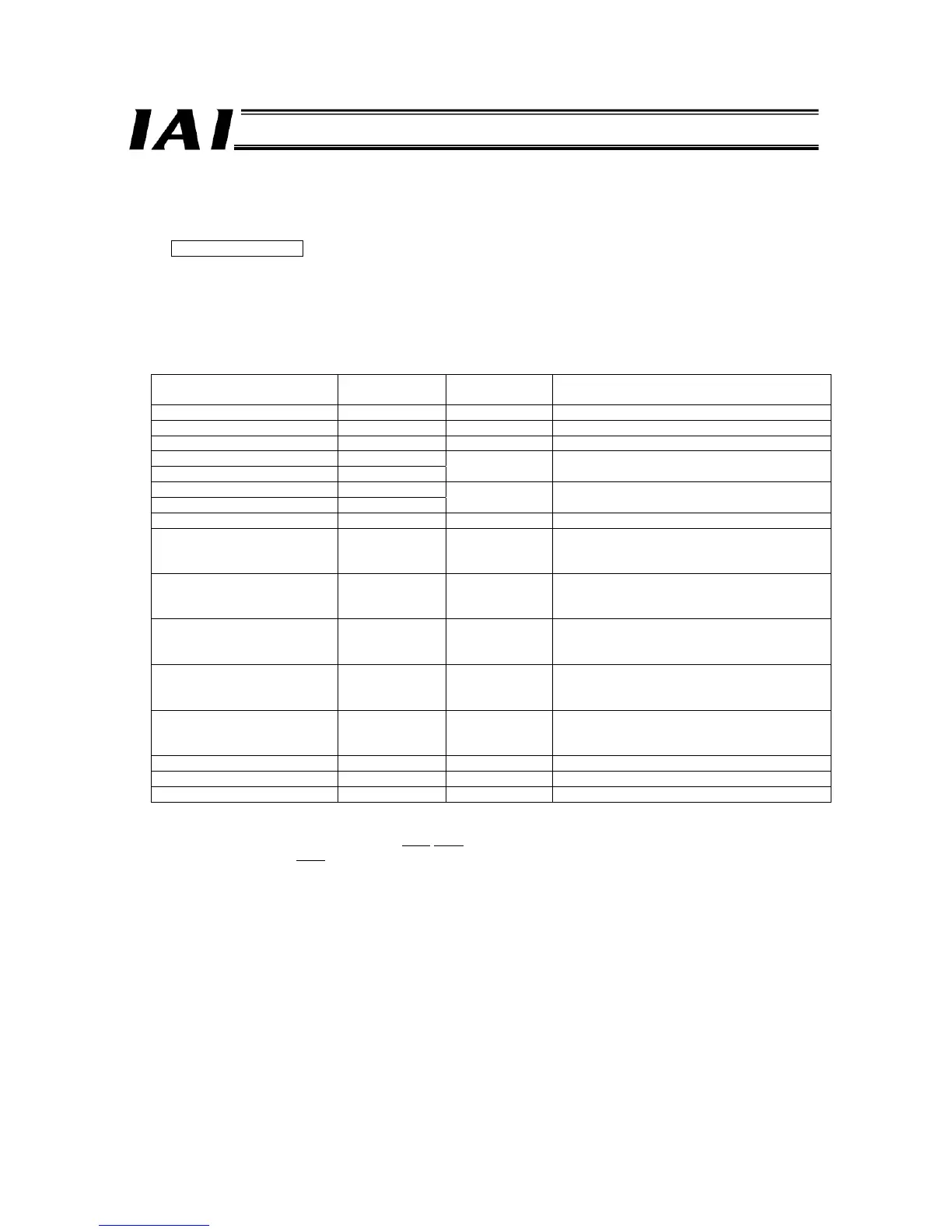
z Target Position Read Query
Field name
RTU mode data
(8 bits)
Data length
(bytes)
Remarks
Header None -
Slave address 3F H 1 Fixed.
Function code 10 H 1
Starting address (upper) F6 H
Starting address (lower) 02 H
2
Initial request command register address of axis
(0)
Number of registers (upper) 00 H
Number of registers (lower) 05 H
2 The number of registers is 5.
Bytes 0A H 1 Number of registers x 2 = 10 (0AH)
New data 1 (upper) 10 H
New data 1 (lower) 40 H
1 each for upper
and lower words
2
Request command (read target position)
New data 2 (upper) 00 H
New data 2 (lower) 0A H
1 each for upper
and lower words
2
Data 0: Position No. 10 is specified.
New data 3 (upper) 00 H
New data 3 (lower) 00 H
1 each for upper
and lower words
2
Data 1: 0
New data 4 (upper) 00 H
New data 4 (upper) 00 H
1 each for upper
and lower words
2
Data 2: 0
New data 5 (upper) 00 H
New data 5 (upper) 00 H
1 each for upper
and lower words
2
Data 3: An axis number is specified (axis 0).
Error check (CRC) 16 bits 2 Based on calculation result (9E46)
Trailer None -
Total bytes 19
Sent Query: 3F10F60200050A 1040
000A 00000000
0000
9E46
Received Response: 3F10F6020005969C

 Loading...


