ecification
<Reading of Response Command Area>
Send a register read (FC = 03H) query.
Sent Query: 3F03F702000512A3
Received Response: 3F030A 1040
000A 27100000 0000 2E8A
Position data
The position data (2710H) written to the position table in [1] has been
read.
Caution
Each gateway command must be cleared after use.
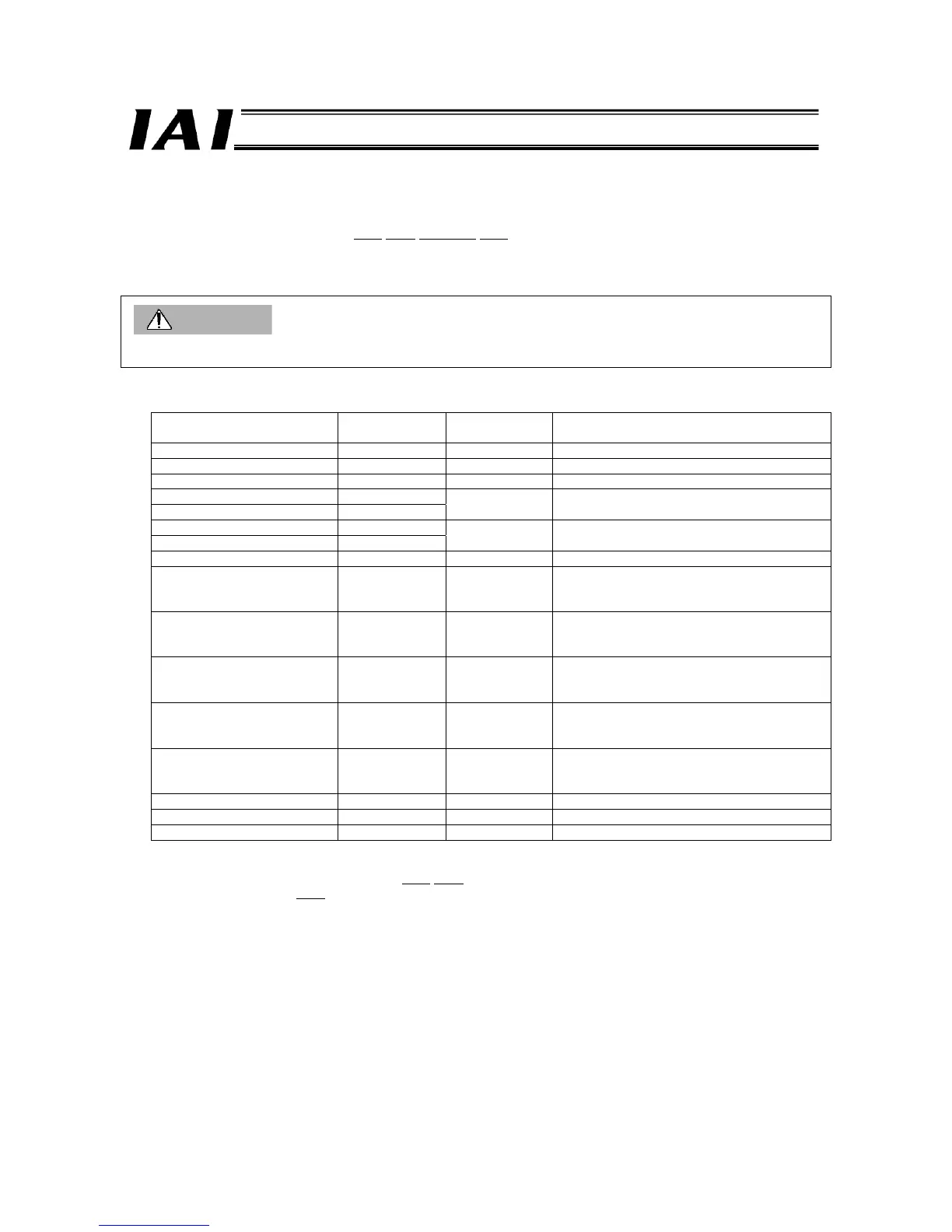
z Positioning Band Read Query
Field name
RTU mode data
(8 bits)
Data length
(bytes)
Remarks
Header None -
Slave address 3F H 1 Fixed.
Function code 10 H 1
Starting address (upper) F6 H
Starting address (lower) 02 H
2
Initial request command register address of axis
(0)
Number of registers (upper) 00 H
Number of registers (lower) 05 H
2 The number of registers is 5.
Bytes 0A H 1 Number of registers x 2 = 10 (0AH)
New data 1 (upper) 10 H
New data 1 (lower) 41 H
1 each for upper
and lower words
2
Request command (read positioning band)
New data 2 (upper) 00 H
New data 2 (lower) 0A H
1 each for upper
and lower words
2
Data 0: Position No. 10 is specified.
New data 3 (upper) 00 H
New data 3 (lower) 00 H
1 each for upper
and lower words
2
Data 1: 0
New data 4 (upper) 00 H
New data 4 (upper) 00 H
1 each for upper
and lower words
2
Data 2: 0
New data 5 (upper) 00 H
New data 5 (upper) 00 H
1 each for upper
and lower words
2
Data 3: An axis number is specified (axis 0).
Error check (CRC) 16 bits 2 Based on calculation result (93D6)
Trailer None -
Total bytes 19
Sent Query: 3F10F60200050A 1041
000A 00000000
0000
9D36
Received Response: 3F10F6020005969C

 Loading...


