To install the frame, do the following:
Attention: It is the service representative’s responsibility to complete the following steps.
1. Before starting the installation, check all cable openings in the floor panel and location of the rubber
bushing holes so that they match the dimensions given in the illustrations on 152.
2. Power off the system and make sure all cables and connectors are disconnected and are not
dangling around the frame. The frame should be free to roll.
3. The floor eyebolts should be already secured to the concrete floor. Verify the height of the center of
the floor eyebolt to the concrete floor or the steel beam/channel adapter mounted to the concrete
floor. Ensure that the turnbuckles can accommodate the total height of the raised floor.
4. Remove the floor tiles around the area where the frame(s) will be installed.
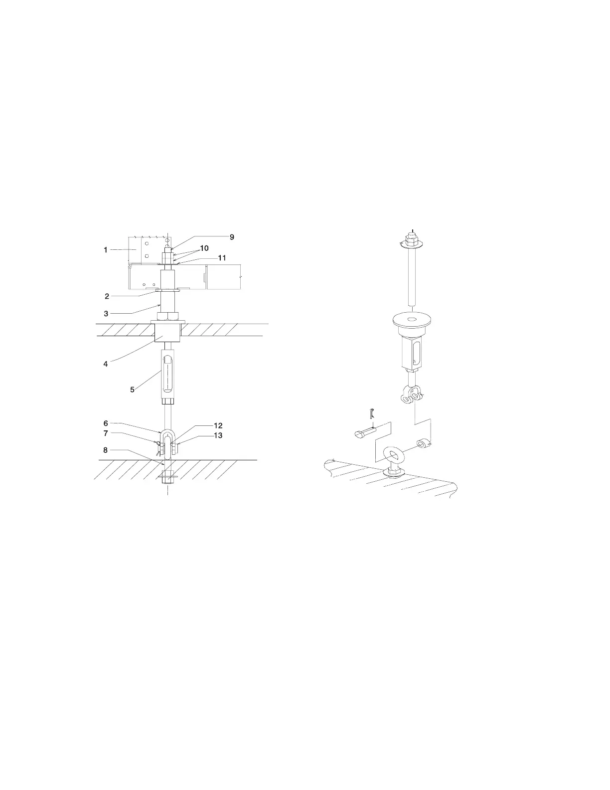
5. Remove the pin and the spacer from the lower jaw (see the following illustrations).
1 Frame 8 Floor Eyebolt (customer-supplied)
2 Jam Nut 9 Threaded Rod
3 Rack Leveler 10 Nut
4 Rubber Bushing 11 Washer
5 Turnbuckle (Short or Long) 12 Spacer
6 Lower Jaw 13 Shaft
7 Pin
Note: The difference between the two turnbuckle assemblies is the length of the turnbuckle.
The Short Turnbuckle Assembly (part number 11P4755) is used for a 9 1/2 inches to 11 3/4
inches raised floor.
The Long Turnbuckle Assembly (part number 11P4756) is used for an 11 3/4 inches to 16
inches raised floor.
6. Place the spacer inside the floor eyebolt and place the floor eyebolt between the lower jaw. Reinstall
the shaft, pin, and spacer.
Chapter 2. Physical Characteristics of Systems 153
 Loading...