Cable Measuring
Accurate measuring of cables is critical to a successful and efficient installation. Do not guess or estimate
your cable lengths.
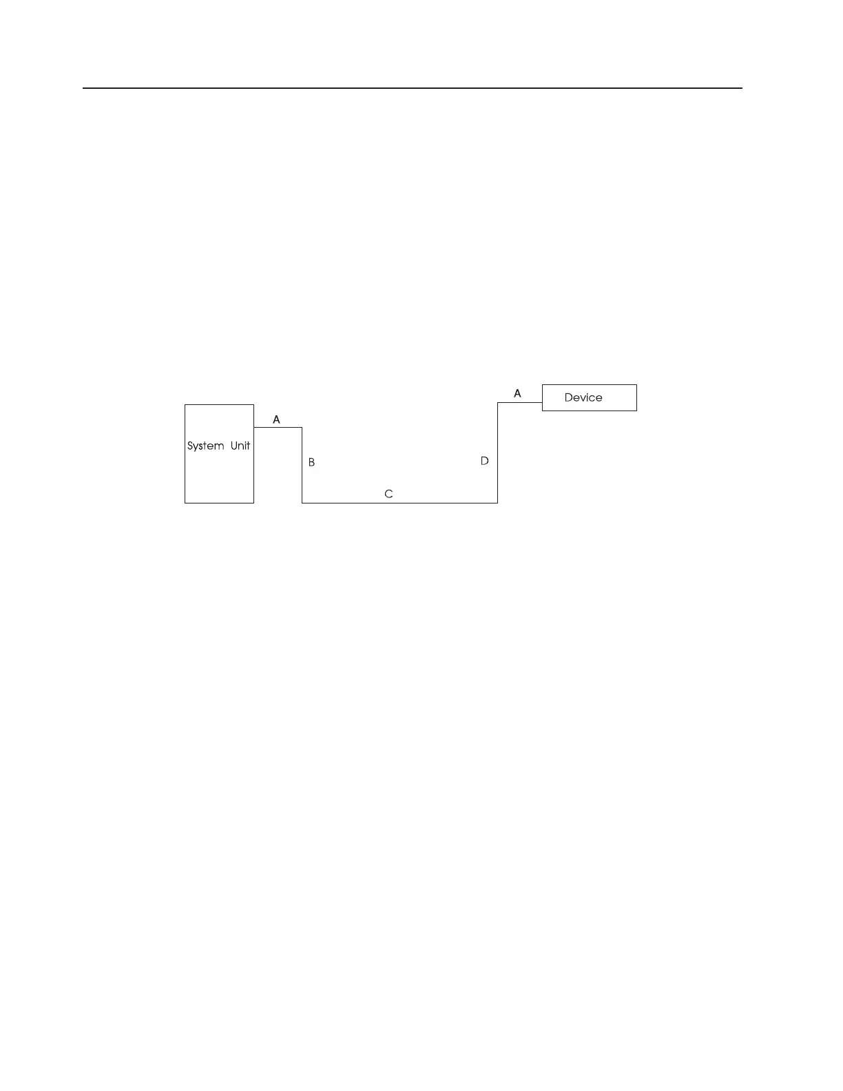
In determining the cable lengths you need, be sure to consider the following:
v A=length allowed for service access, 51 mm (2 ft.) on both system unit and device ends.
v B=length from system unit to floor.
– Tabletop to floor for desktop models.
– 46 mm (1.5 ft.) for deskside units.
– See ″7015 Considerations″ for rack-mounted system units.
v C=horizontal and vertical cable runs. Be sure to route cables around furniture to avoid tripping hazards.
v D=distance from floor to device. (This can include distance between floors, between buildings, and so
on, depending on complexity of installation.)
7015 Considerations
The 78-pin multiport interface cables for the 8-or 16-port Async Adapters when used with the 7015 Models
R10 and R20 attach to the system tailgate connect rather than to the adapter itself. Internal cables not
shown in the following cable diagram run from the adapter through the cable management arm to the
tailgate connector. You should begin your cable-measurements at the tailgate connector for the 8-or
16-port Async Adapter multiport cables.
Other cables used with the 7015 Models R10 and R20 are routed through a cable management arm. The
management arm is designed to ensure that the cables do not kink, stretch, or accidentally disconnect
when a drawer is pulled out for service.
When planning the necessary lengths of cables routed through this arm, add 2.3 m (7.5 ft.) to the
measured distance from the base of the rack.
350 Site and Hardware Planning Information
 Loading...