Chapter 4. Central processor complex I/O system structure 153
Table 4-4 illustrates the AID assignment for each fanout slot relative to the drawer location on
a new build system.
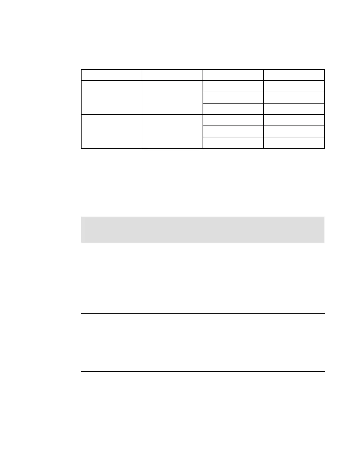
Table 4-4 AID number assignment
Fanout slots
The fanout slots are numbered LG03 - LG14 left to right, as shown in Table 4-4. All fanout
locations and their AIDs for two drawers are shown in Table 4-4 for reference only. Slots LG01
and LG16 never have a fanout installed because they are dedicated for FSPs. Slots LG02 and
LG15 are reserved.
The AID assignment is listed in the PCHID REPORT that is provided for each new server or
for an MES upgrade on existing servers.
Example 4-1 shows part of a PCHID REPORT for a Model N20. In this example, one fanout is
installed in the first drawer (location A21A slot LG03) and one fanout is installed in the second
drawer (location A25A slot LG11). The assigned AID for the fanout in the first drawer is 1B.
The AID that is assigned to the fanout in the second drawer is 15.
Example 4-1 AID assignment in PCHID REPORT
CHPIDSTART
12345678 PCHID REPORT Oct 31,2014
Machine: 2965-N20 SNXXXXXXX
- - - - - - - - - - - - - - - - - - - - - - - - - - - - - - - - - - - - - - -
Source Cage Slot F/C PCHID/Ports or AID Comment
A21/LG03 A21A LG03 0172 AID=1B
A25/LG11 A25A LG11 0172 AID=15
Drawer Location Fanout slot AIDs
First A21A LG03-LG06 (PCIe)
a
a. For Model N10, only the first drawer’s LG09-LG10 are supported for IFB, and LG11-LG14 are supported
for PCIe.
1B-1E
LG07-LG10 (IFB)
a
04-07
LG11-LG14 (PCIe) 1F-22
Second A25A LG03-LG06 (PCIe) 11-14
LG07-LG10 (IFB) 00-03
LG11-LG14 (PCIe) 15-18
Important: The AID numbers in Table 4-4 are valid only for a new build system or if a
second CPC drawer is added. If a fanout is moved, the AID follows the fanout to its new
physical location.
 Loading...