IDEC SmartRelay functions
188 IDEC SmartRelay Manual
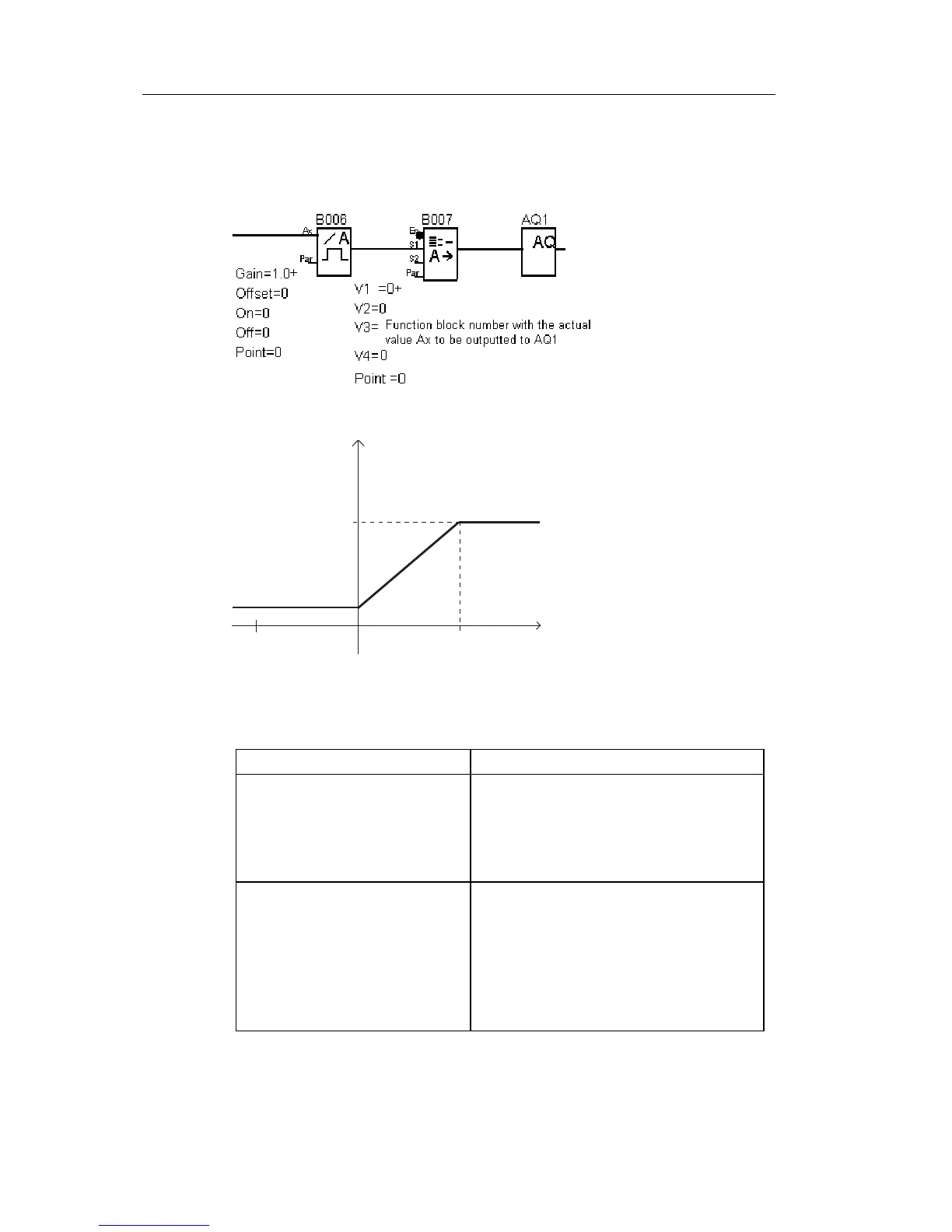
In the block diagram below, the analog output module
operates as the lower part of the timing chart.
(example):
Set each parameter of the functions referring to the table
below.
Parameters
Analog trigger
(B006 in the above table)
A : Gain = + 1.00
B : Offset = 0
On : On threshold = 0
Off : Off threshold = 0
p : Number of decimals: arbitrary
Analog Multiplexer
(B007 in the above table)
V1 = 0
V2 : arbitrary
V3 = Function block number with the
actual value Ax to be outputted
from AQ1
V4 : arbitrary
p : Number of decimals: arbitrary
 Loading...
