Technical data
IDEC SmartRelay Manual 259
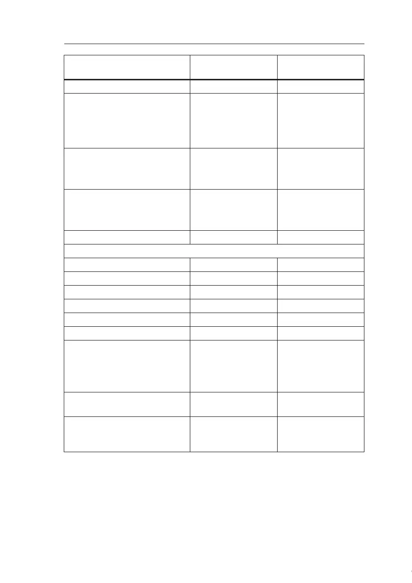
Input voltage L1
Signal 0
Signal 1
Signal 0
Signal 1
< 40 V AC
> 79 V AC
< 30 V DC
> 79 V DC
< 40 V AC
> 79 V AC
< 30 V DC
> 79 V DC
Input current at
Signal 0
Signal 1
< 0.03 mA
> 0.08 mA
< 0.03 mA
> 0.08 mA
Delay time at
0 to 1
1 to 0
typ. 50 ms
typ. 50 ms
typ. 50 ms
typ. 50 ms
Line length (unshielded) 100 m 100 m
Digital outputs
Number 4 4
Output type Relay outputs Relay outputs
Electrical isolation Yes Yes
In groups of 1 1
Control of a digital input Yes Yes
Continuous current I
th
max. 10 A per relay max. 5 A per relay
Incandescent lamp load
(25000 switching cycles) at
230/240 V AC
100/120 V AC
1000 W
500 W
1000 W
500 W
Fluorescent tubes with ballast
(25000 switching cycles)
10 x 58 W
(at 230/240 V AC)
10 x 58 W
(at 230/240 V AC)
Fluorescent tubes, convention-
ally compensated
(25000 switching cycles)
1 x 58 W
(at 230/240 V AC)
1 x 58 W
(at 230/240 V AC)
FL1C-H12RCC
FL1C-B12RCC
FL1B-M08C2R2
Courtesy of Steven Engineering, Inc. ● 230 Ryan Way, South San Francisco, CA 94080-6370 ● General Inquiries: (800) 670-4183 ● www.stevenengineering.com
 Loading...
