Technical data
IDEC SmartRelay Manual 269
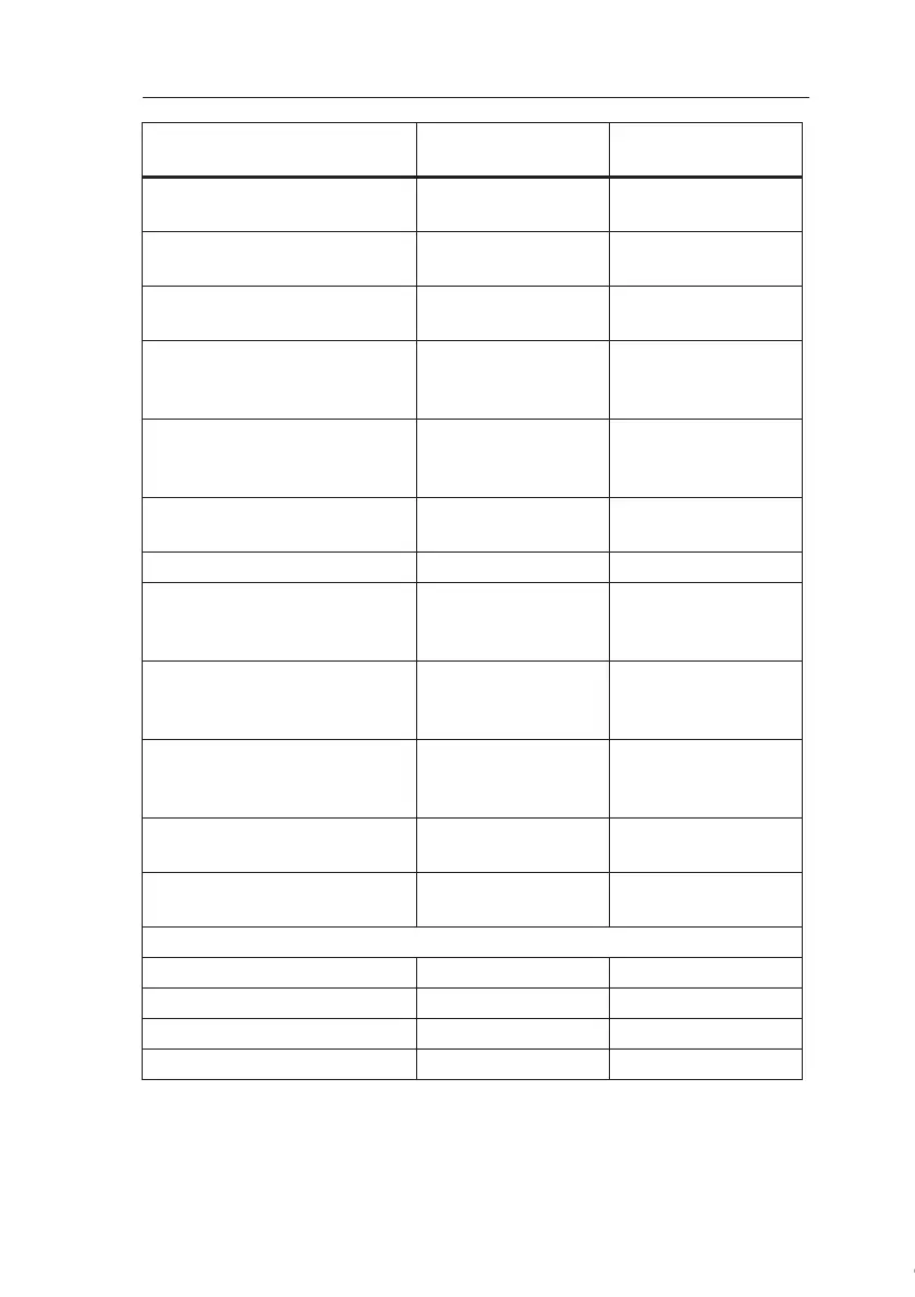
Continuous current I
th (per termi-
nal)
max. 10 A per relay max. 5 A per relay
Incandescent lamp load
(25000 switching cycles) at
1000 W 1000 W
Fluorescent tubes with ballast
(25000 switching cycles)
10 x 58 W 10 x 58 W
Fluorescent tubes,
conventionally compensated
(25000 switching cycles)
1 x 58 W 1 x 58 W
Fluorescent tubes, uncom-
pensated
(25000 switching cycles)
10 x 58 W 10 x 58 W
Short circuit–proof and
overload–proof
Short–circuit current limitation
Derating none; across the en-
tire temperature
range
none; across the en-
tire temperature
range
Short circuit–proof cos 1 Power protection
B16
600A
Power protection
B16
600A
Short–circuit proof cos 0.5 to
0.7
Power protection
B16
900A
Power protection
B16
900A
Parallel output circuits for
power increase
Not permitted Not permitted
Protection of output relay
(if desired)
max. 16 A,
characteristic B16
max. 16 A,
characteristic B16
Switching rate
Mechanical 10 Hz 10 Hz
Electrical
Ohmic load/lamp load 2 Hz 2 Hz
Inductive load 0.5 Hz 0.5 Hz
FL1C-H12RCE
FL1C-B12RCE
FL1B-M08B2R2
Courtesy of Steven Engineering, Inc. ● 230 Ryan Way, South San Francisco, CA 94080-6370 ● General Inquiries: (800) 670-4183 ● www.stevenengineering.com
 Loading...
