IDEC SmartRelay installation and wiring
IDEC SmartRelay Manual 33
IDEC SmartRelay with transistor outputs
IDEC SmartRelay versions with transistor outputs can be
identified by the fact that the letter R is missing from their
type name. The outputs are short circuit-proof and over-
load-proof. An auxiliary load voltage supply is not necessary,
because IDEC SmartRelay supplies the load voltage.
Requirements for transistor outputs
The load connected to IDEC SmartRelay must have the fol-
lowing characteristics:
• The maximum switched current is 0.3 A per output.
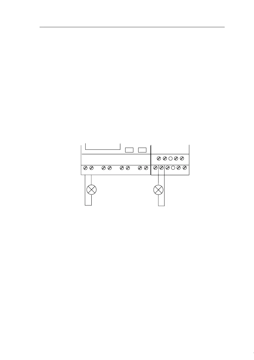
Connecting
This is how you connect the load to a IDEC SmartRelay with
transistor outputs:
Q1 Q2MM
Q5 Q6MM
load
Load: 24 V DC, 0.3 A max.
load
Courtesy of Steven Engineering, Inc. ● 230 Ryan Way, South San Francisco, CA 94080-6370 ● General Inquiries: (800) 670-4183 ● www.stevenengineering.com