INFICON Product Overview | 5
074-594-P1H Micro GC Fusion Operating Manual 29 / 319
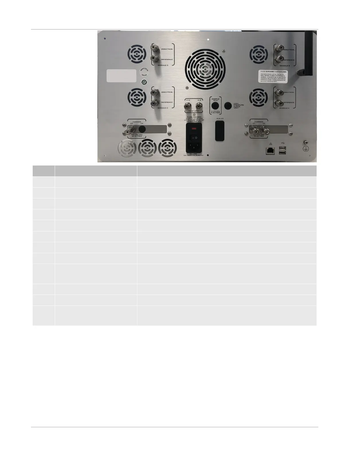
Number Label Description
1 SAMPLE INLET Optional 1/8 in. unheated rear sample inlet
2 CARRIER C1, C2, C3 and C4 Carrier gas connections with 1/8 in. Swagelok connectors
3 ANALYTICAL Vents for the analytical column(s) with 1/8 in. Swagelok connectors
4 REFERENCE Vents for the reference column(s) with 1/8 in. Swagelok connectors
5 PUMP VENT Vent for the pump (black)
6 HIGH PRESSURE VENT Vent for the integrated sample conditioner (if configured)
7 Wi-Fi Antenna Boost wireless signal strength and improves connectivity
8 RJ-45 LAN connector Wired LAN connection
9 AUX I/O The auxillary I/O interface can be configured to remotely start or
cancel sample runs
10 USB connectors Two USB interfaces are provided
11 Grounding Connect to the grounding when installed in a rack
12 120/250V - 10A 50-60HZ 120-250 VAC power cord connection, with a 10A 250V replaceable
fuse and a power on/off switch
An optional rack mounting kit (PN 952-4100-G1) is available which allows the 4-
module chassis to be mounted on a 19 in. rack mount. See Installing the Rack Mount
Kit [
}71].

 Loading...