6 | Installation INFICON
56 / 319 074-594-P1H Micro GC Fusion Operating Man-
ual
6 Installation
6.1 Site Preparation
Proper site preparation prior to installing Micro GC Fusion is critical. Contact INFICON
(www.inficon.com) with any questions regarding site preparation.
Bullet points (.) identify hardware that must be available and actions that must
be addressed when installing Micro GC Fusion.
6.1.1 List of Required Tools
The following tools are user supplied:
• 1 1/8 in. wrench recommended, or adjustable large wrench (for attaching regulator
to gas tank)
• Teflon® tape for regulator connections
• 1/16 in. tubing and fittings for connection to the sample inlet
• Philips #2 screwdriver (for rack mounting)
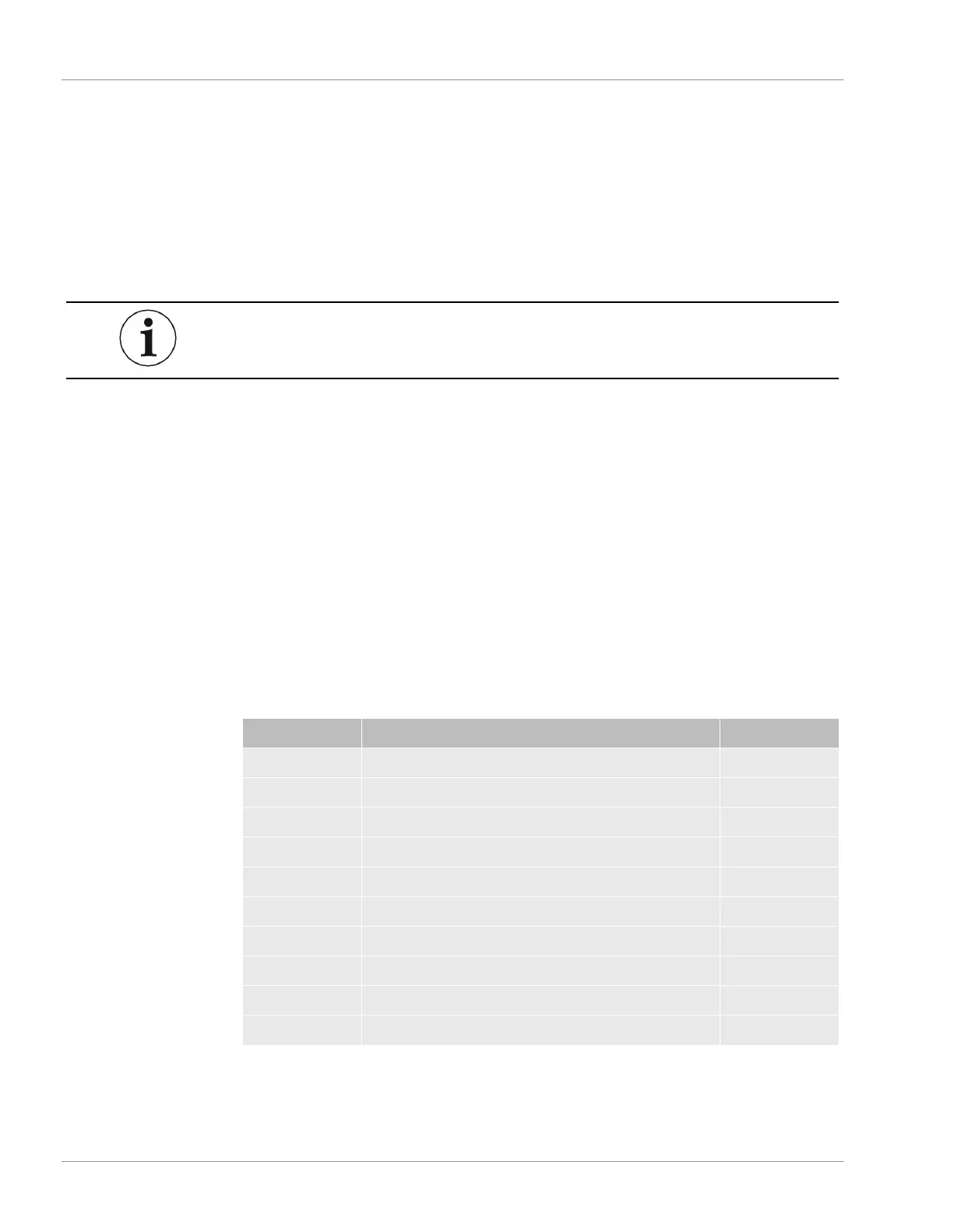
The following tools and parts are included in the optional Install Kit (PN 952-021-G1)
to facilitate installation. If the optional install kit was not purchased, the tools and parts
below must be provided by the user upon installation.
PN Description Quantity
059-0442 Ball valve, 2-way. 0.125-tube brass RoHS 2 pc
059-0449 Union tee, 0.125-Tube, 0.437 nut brass RoHS 1 pc
059-0554 Nut, 0.125-Tube, 0.437 Hex, 0.47 Lg Brass RoHS 4 pc
059-0714 Ferrule set, 0.125-Tube 10 pack brass RoHS 4 pc
069-0115 Copper tubing, 0.128 OD, 0.065 ID 1 pc
070-1999 Hex driver, 2.5 mm ball point L-handle SS RoHS 1 pc
070-2000 Tubing cutter, 0.125 to 0.625 OD tubes, RoHS 1 pc
070-2002 Wrench combination, 0.312 steel RoHS 2 pc
070-2003 Wrench combination, 0.437 steel RoHS 2 pc
070-2004 Wrench combination, 0.562 steel RoHS 1 pc

 Loading...