= 0000000000011100000000000000000000
= 0x700000
Page 1 end address = 0x00352E30 appends with 2’b11
= 0000000000110101001011100011000011
= 0xD4B8C3
The start and end address must be correlated with the start and end address for each
page printed in the .map file.
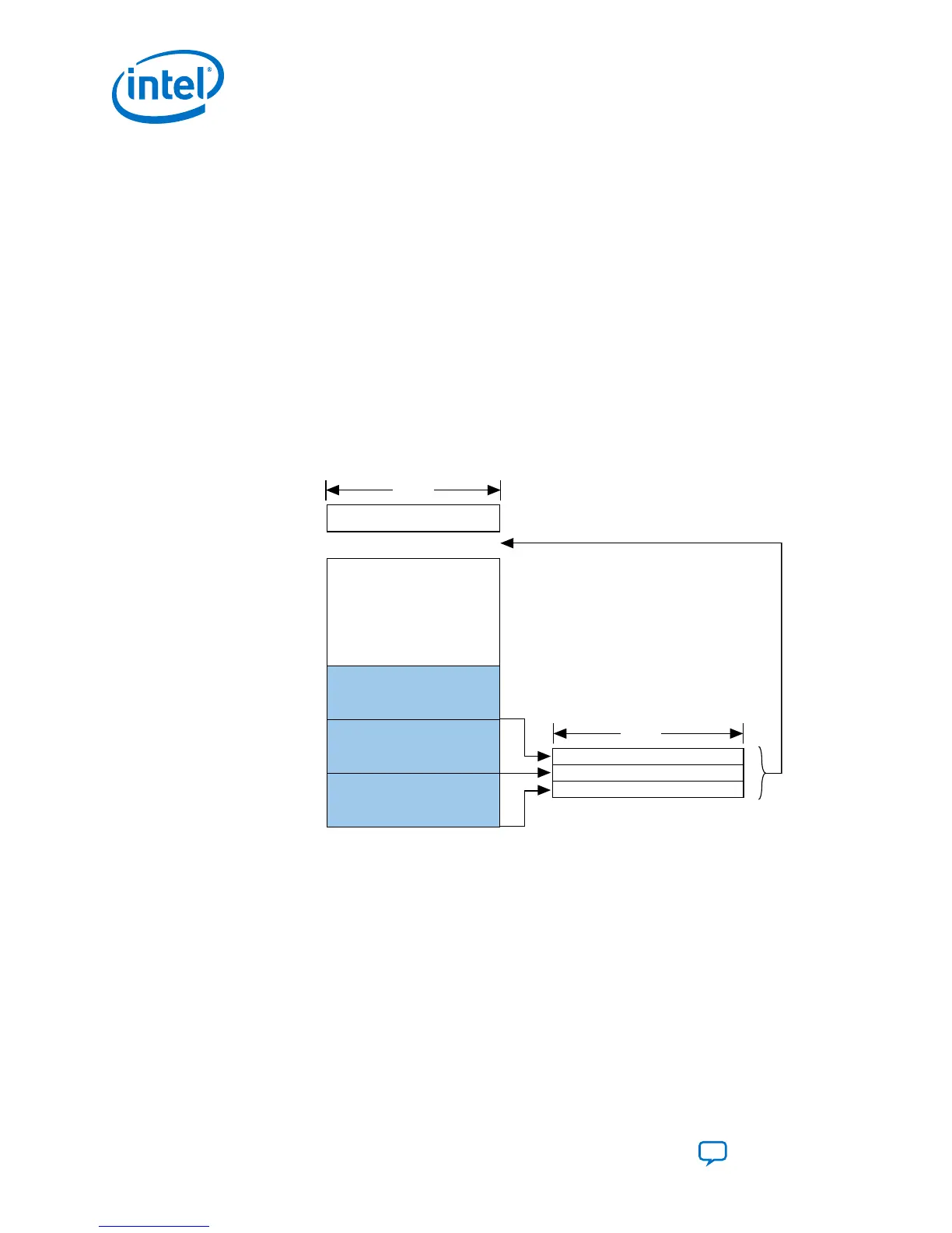
3.1.6.1.7. Implementing Page Mode and Option Bits in the CFI Flash Memory Device
Figure 18. Implementing Page Mode and Option Bits in the CFI Flash Memory Device
• The end address depends on the density of the flash memory device. For the address range for devices
with different densities, refer Byte Address Range table.
• You must specify the byte address for the option bits sector.
Option Bits
Configuration Data (Page 2)
Configuration Data (Page 1)
Configuration Data (Page 0)
Page 2 Address + Page-Valid
Page 1 Address + Page-Valid
Page 0 Address + Page-Valid
End Address
0x000000
8 Bits
32 Bits
Use the parameter editor to set the option bits on the FPGA Configuration tab of
Parallel Flash Loader II Intel FPGA IP.
3. Intel Stratix 10 Configuration Schemes
UG-S10CONFIG | 2018.11.02
Intel Stratix 10 Configuration User Guide
Send Feedback
40
 Loading...