•
If you select absolute addressing mode, the data in the .hex is
programmed in the flash memory device at the same address location
listed in the .hex.
• If you select relative addressing mode, specify a start address. The data in
the .hex is programmed into the flash memory device with the specific
start address, and the differences between the addresses are kept. If no
address is specified, the software selects an address.
Note:
You can also add other non-configuration data to the .pof by selecting
the .hex that contains your data when creating the flash memory
device .pof.
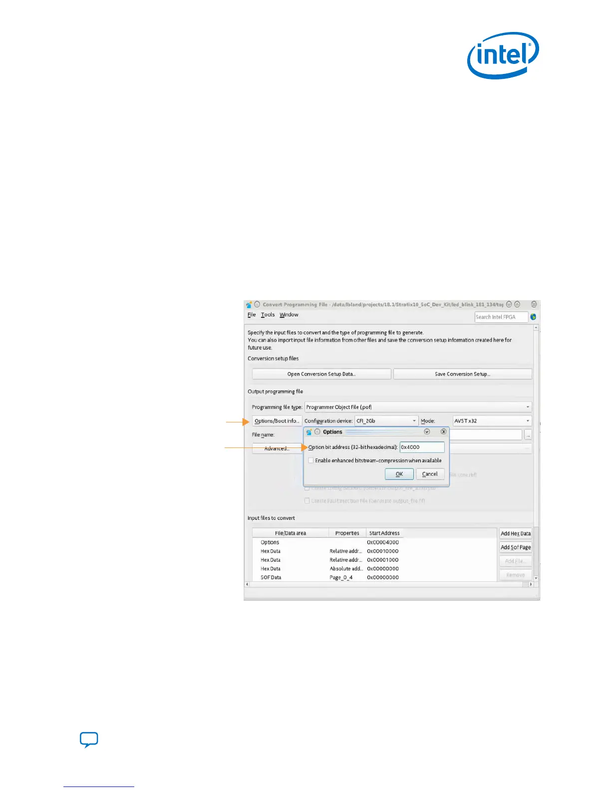
9. Click Options/Boot info to specify the start address to store the option bits.
This start address must be identical to the address you specify when creating the
PFL II IP core. Ensure that the option bits sector does not overlap with the
configuration data pages and that the start address resides on an 8-KB boundary.
Figure 20. Convert Programming File - Options Bit Address
Options/Boot info...
Options bit address
10. To generate programming files with the enhanced bitstream compression feature,
turn on the Enable enhanced bitstream-compression when available in the
Options dialog box and click OK.
11.
Click Generate to create the .pof.
3. Intel Stratix 10 Configuration Schemes
UG-S10CONFIG | 2018.11.02
Send Feedback
Intel Stratix 10 Configuration User Guide
43
 Loading...