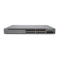
Table 11: Link/Activity LED on the Management Port on an EX3300 Switch
State and DescriptionColorLED
•
Blinking—The port and the link are active, and there is link
activity.
•
On steadily—The port and the link are active, but there is no
link activity.
•
Off—The port is not active.
GreenLink/Activity
Table 12 on page 21 describes the Status LED.
Table 12: Status LED on the Management Port on an EX3300 Switch
State and DescriptionLCD IndicatorLED
Indicates the speed. The speed indicators are:
•
One blink per second—10 Mbps
•
Two blinks per second—100 Mbps
•
Three blinks per second—1000 Mbps
SPDStatus
Related
Documentation
Connecting a Switch to a Network for Out-of-Band Management on page 109•
Power Supply in EX3300 Switches
The power supply in EX3300 switches is built in along the rear panel of the chassis, with
an AC power cord inlet or DC power terminal block on the rear panel to connect power
to the switch.
NOTE: After powering on the switch, wait for at least 60 seconds before
powering it off. After powering off the switch, wait for at least 60 seconds
before powering it back on.
After the switch has been powered on, it can take up to 60 seconds for status
indicators—suchasshow chassis command output and messages on the LCD
panel—to indicate that the power supply is functioning normally. Ignore error
indicators that appear during the first 60 seconds.
Table 13 on page 21 lists the power consumed by each EX3300 switch model. The
maximum power available on a PoE+ port is 15.4 W.
Table 13: Power Consumed by EX3300 Switches
Maximum System Power
Available for PoE
Maximum Power
Consumed by the Switch
Number of PoE-Enabled
PortsModel Number
–50 W–EX3300-24T
21Copyright © 2015, Juniper Networks, Inc.
Chapter 2: Component Descriptions

 Loading...