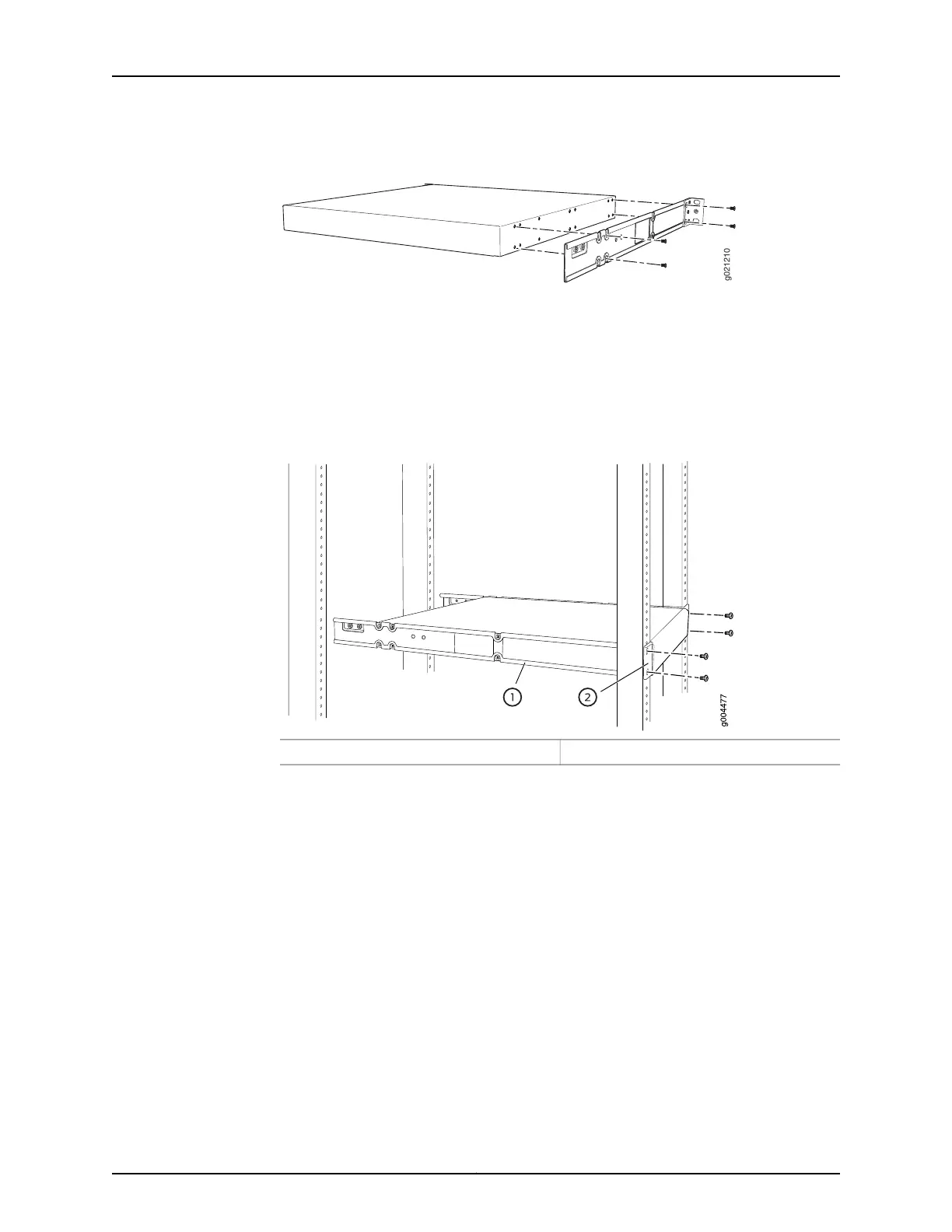
Figure 25: Attaching the Side Mounting-Rail to the Switch Chassis
6. Insert the 4x6-mm Phillips flat-head mounting screws into the remaining two holes
in the side mounting-rails and tighten the screws.
7. Have one person grasp both sides of the switch, lift the switch, and position it in the
rack, aligning the side mounting-rail holes with the threaded holes in the front post
of the rack. Align the bottom hole in both the front-mounting brackets with a hole in
each rack rail, making sure the chassis is level. See Figure 26 on page 89.
Figure 26: Mounting the Switch to the Front Posts in a Rack
2—1— Front-mounting bracketSide mounting-rail
8. Have a second person secure the front of the switch to the rack by using the appropriate
screws for your rack.
9. Slide the rear mounting-blades into the side mounting-rails. See Figure 27 on page 90.
89Copyright © 2015, Juniper Networks, Inc.
Chapter 9: Installing the Switch