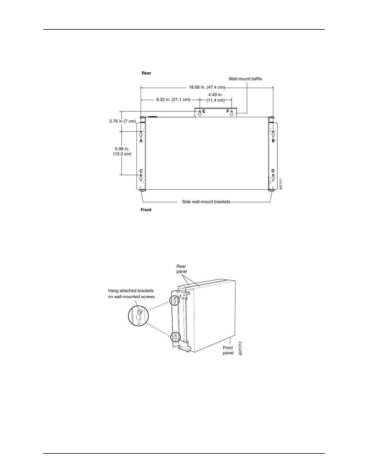
Figure 30: Measurements for Installing Mounting Screws
18.68 in. (47.4 cm)
Front
Rear
A
E F
C
B
D
Side wall-mount brackets
8.32 in. (21.1 cm)
4.49 in.
(11.4 cm)
5.98 in.
(15.2 cm)
2.76 in (7 cm)
g021211
Wall-mount baffle
5. Lift the unit (one switch or two) by grasping each side, and hang the unit by attaching
the brackets to the mounting screws as shown in Figure 31 on page 94.
6. Tighten all mounting screws.
Figure 31: Mounting the Switch on a Wall
g021212
Hang attached brackets
on wall-mounted screws.
Front
panel
Rear
panel
Related
Documentation
• Connecting AC Power to an EX3300 Switch on page 105
• Connecting DC Power to an EX3300 Switch on page 107
• Connecting and Configuring an EX Series Switch (CLI Procedure) on page 119
• Wall-Mounting Warning for EX3300 Switches on page 169
Copyright © 2015, Juniper Networks, Inc.94
Complete Hardware Guide for EX3300 Ethernet Switches