4 Control Connections
4.1 Connection and Control Elements
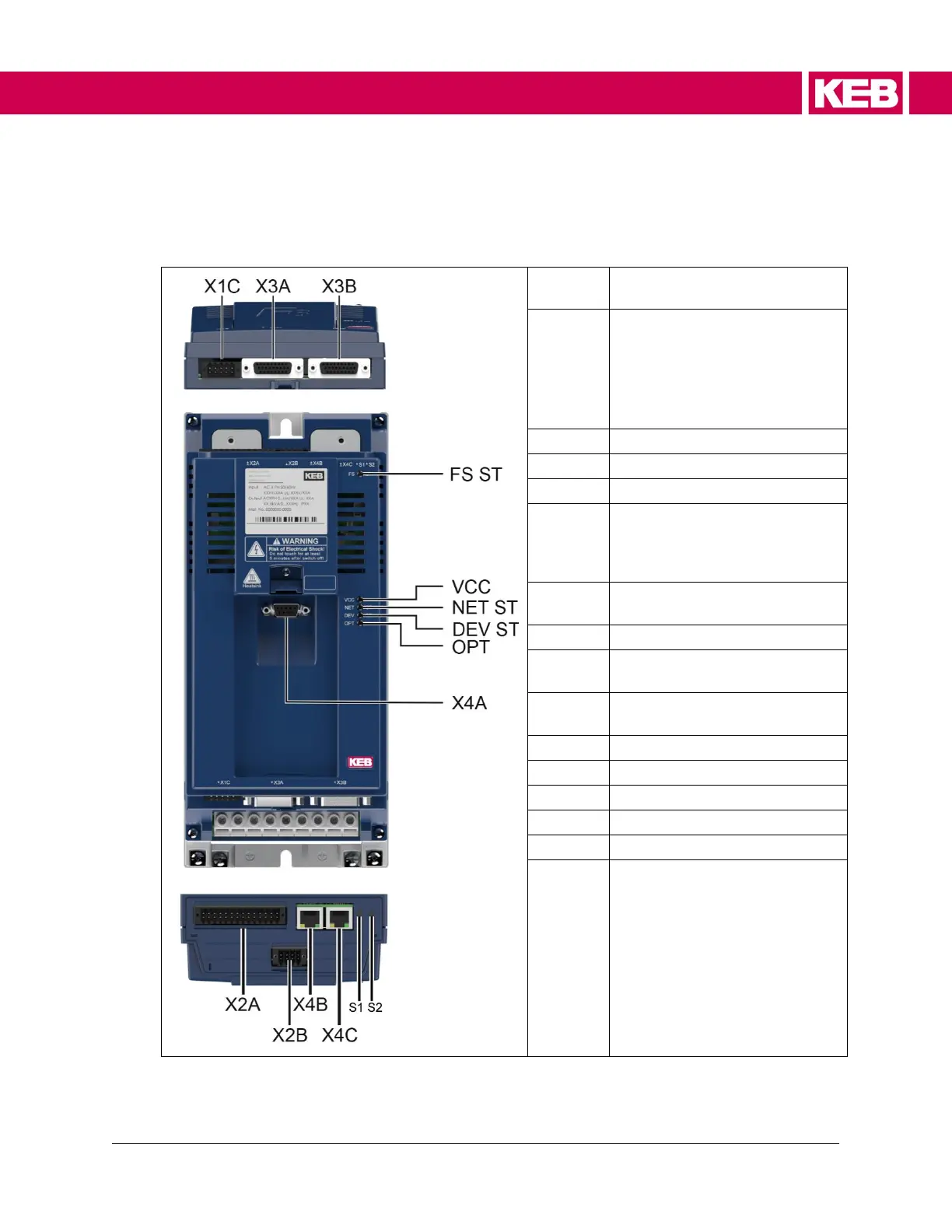
Temperature monitoring, brake
control/ monitoring
• Control terminal block for
digital inputs/outputs
• 24V supply
• Relay output
• Analog inputs and outputs
• CAN bus
Encoder interface channel A
Encoder interface channel B
Diagnostic interface with
RS232/485 interface according
operator slot
Fieldbus input / port 0 / RS485
potential-free
Rotary coding switch 1
(Low-Byte)
Rotary coding switch 2
(High-Byte)
LED network / fieldbus status
LED Inverter / device status
Figure 4. Connection and control elements