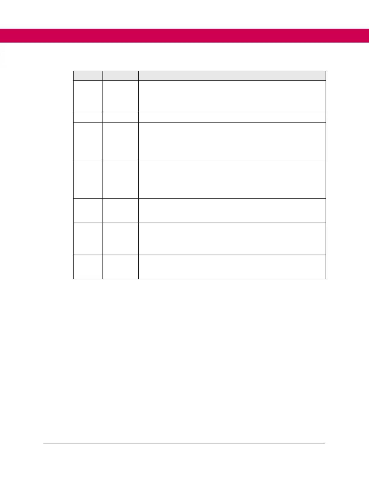
Sin+/-
Cos+/-
Sin_abs+/-
Cos_abs+/-
Only channel A:
Input for sinusoidal absolute signals Uss=1 V for SinCos encoder Uss=3.8
V maximum for resolver
Output for clock signal RS485
Only channel A:
Output field voltage for resolver:
• Ueff=2.54 V ≙ Uss=7.2 V ±5 %; max. Ieff=30 mA; 10 kHz
• Coupling factor for resolver: 0.5 ±10 %
• Phase shifting 0° ±5°
Output supply voltage for encoder:
• ec14 = 0 => 5.25 V +5 %/ -10 %
• ec14 = 1 => 8 V +5 %/ -10 %
• ec14 = 2 => automatically, depending on the set encoder type (ec16)
• Max. 500 mA total (250 mA per channel)
Output supply voltage for encoder:
• 5.25 V +5 %/ -10 %
• Max. 500 mA total (250 mA per channel)
Output supply voltage for encoder:
Udc=24 V max. 500 mA total (250 mA per channel)
• Minimum P24V_IN - 3 V
• Maximum P24V_IN
A_HTL+/-
B_HTL+/-
N_HTL+/-
Only channel B:
Input HTL signals 10 V maximum 150 kHz
4.5 Diagnostic Interface X4A
The integrated RS232/485 interface serves for the connection of service tools (e.g.,
COMBIVIS) displays or the F6 operator. Protocol DIN 66019II is used as communication
protocol.
4.6 Fieldbus Interface X4B
The fieldbus interface X4B supports the following protocol:
RS485 potential-free DIN66019II KEB Elevator Application Layer
4.7 Fieldbus Interface X4C
The interface X4B supports the following protocol:
Ethernet TCP/IP