EasyManuals Logo

KEB F6 User Manual

KEB F6
305 pages
To Next Page IconTo Next Page
To Previous Page IconTo Previous Page
Page #38 background imageLoading...
Page #38 background image
Control Connections
38
© 2024 KEB America, Inc.
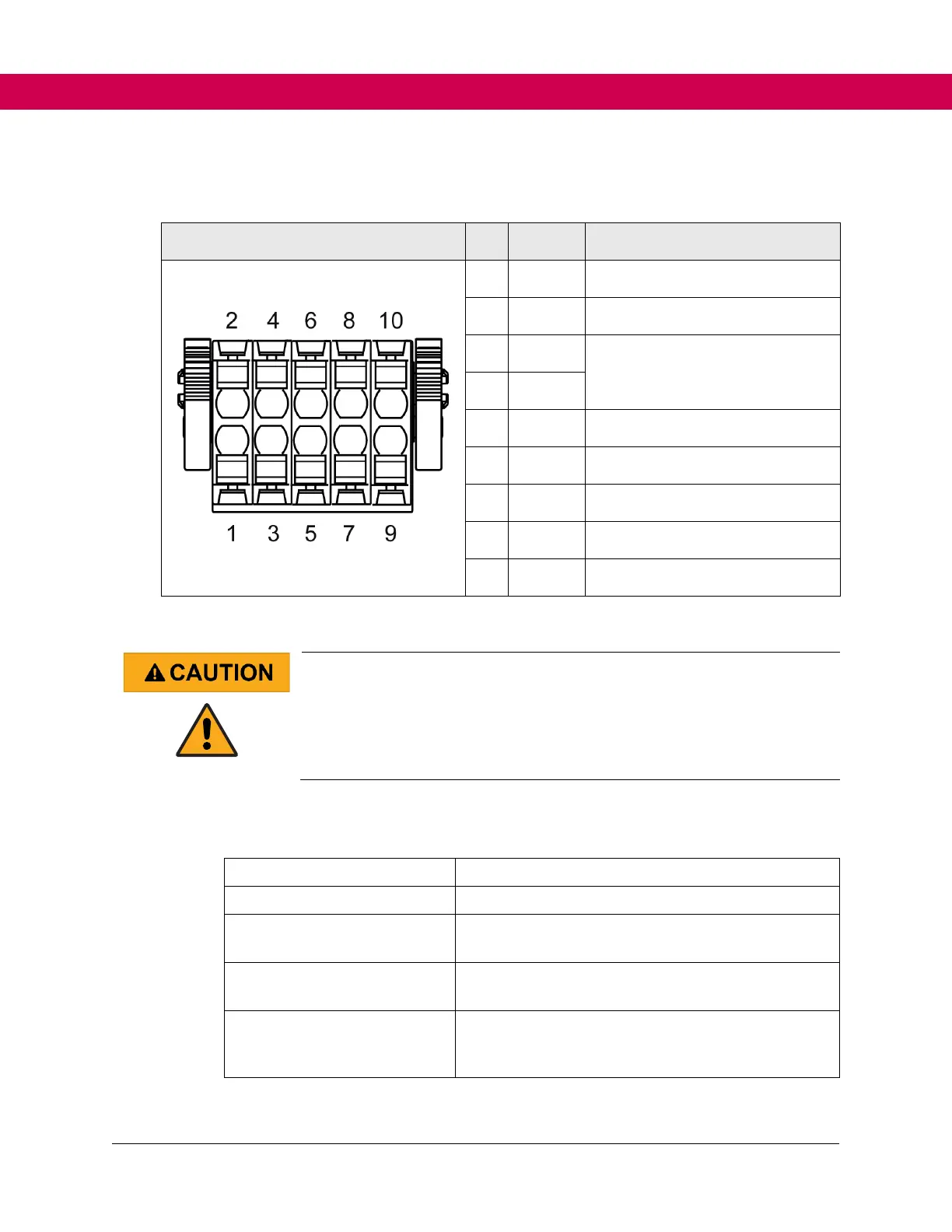
4.2 Motor Monitoring X1C (temperature, brake)
X1C
PIN
Name
Description
1
BR+
Brake Control / Output +
2
BR-
Brake Control / Output -
3
0V
For supplying the feedback inputs
P24Vin - 0.5V / max. 1A
(BR+ and 24Vout in total 2A)
4
24Vout
5
DIBR1
Feedback Input for Brake Control
6
DIBR2
Feedback Input for Brake Control
7/8
reserved
-
9
TA1
Temperature Detection / Output +
10
TA2
Temperature Detection / Output -
Figure 5. Assignment of X1C
Wrong dimensioning of the load on the brake output!
Brake does not release or only with delay!
Ensure the operating voltage of the brake or contactor falls within the
tolerance of the 24V supply of the drive control.
Use pilot relays if necessary.
4.2.1 Specification brake/relay output
Name
BR+ (X1C.1); BR- (X1C.2)
Function
Output to control one/two brake(s) or contactors.
Output Voltage (DC)
Minimum P24Vin 1.2V
Maximum P24Vin
Maximum Output Current
One load: 2 A
Two load
Others
Internal free-wheeling path
Internal filter circuit
Not short circuit proof

Table of Contents

Questions and Answers:

Question and Answer IconNeed help?

Do you have a question about the KEB F6 and is the answer not in the manual?

KEB F6 Specifications

General IconGeneral
CategoryInverter
Protection ClassIP20
Communication InterfacesPROFIBUS, CANopen, RS485
Operating Temperature-10°C to +50°C
SeriesF6
Output Frequency0 Hz to 600 Hz
Protection FeaturesOvercurrent, Overvoltage, Undervoltage, Short circuit
Humidity5% to 95% (non-condensing)
AltitudeUp to 1000 m above sea level
Control ModesSensorless vector control
Storage Temperature-25°C to +70°C

Related product manuals