MCC Input
The MCC input function monitors the status on the contactor in both the idle mode and
operational modes. If used, the input must be connected to a Normally Closed (NC)
auxiliary contact on the motor contactor. The drive must see the contact is closed while
the system is idle to allow a new operational sequence. If the MCC input is not active
during the idle mode or becomes active during run mode, a drive fault is triggered.
MCC Output + Input
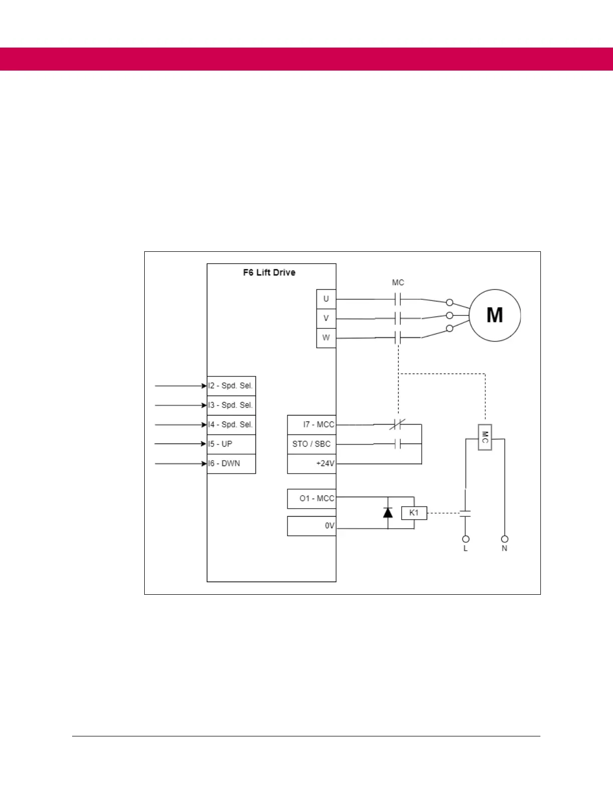
When used in combination, the following diagram shows an example of the connection.
Figure 18. MCC output + input connection
Speed Selection
When the US04 Control Type = binary speed selection (1) or digital speed selection (0),
the X2A terminal strip inputs to be used for speed selection must be assigned with LI04-
11. For binary speed selection, three inputs will need to be assigned speed selection (27)
and for digital speed selection, five inputs will need to be assigned as speed selection.
For the inputs assigned as speed selection, the priority will be: I1>I2>....I8.