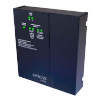
Keyscan Inc. A Member of the Kaba Group – CA150 Rev. B Installation Guide (07.15)
DIP Switch/Jumper Settings
The CA150 has DIP switches and jumpers that activate or alter specific board functions to meet installation
requirements.
System configuration DIP switches S1.1 to S1.12 – page 36
Reader configuration DIP switches S2.1 – S2.6 – page 40
Input supervision DIP switches S2.7 & S.8 – page 47
System software mode DIP switches S2.9 – S2.10 – page 48
Restore factory defaults jumper J1 (Clear memory) – page 49
System reset jumper J6 – page 50
Door relays – powered/unpowered jumpers J8/J9 – page 50
AUX relay – powered/unpowered jumpers J10/J11 – page 50
Accessibility output relay – page 51
Depending on the installation, some jumpers may require activation in order to enable the desired settings.
After you have installed and connected the control board with a power source, be sure to reset the factory
defaults by clearing memory. This procedure is reviewed later in this section.
S1.1 – S1.12 – System Configuration DIP Switches
The following outlines the functions that system configuration DIP switches S1.1 to S1.12 regulate. Refer to
Table 3 – System Configuration DIP Switch S1 Settings on page 38 for function activation and DIP switch
settings.
S1.1 - Communication Mode
Keyscan CA150 control boards support serial, network and reverse network communication modes. Serial and
network communication use standard polling in which communication is initiated at the communication
manager server. Reverse network communication differs from standard polling in that communication is
initiated at the control unit. Do not set the S1.1 switch for reverse network communication unless a license
was purchased from Keyscan.
S1.2 - Communication Bit Rate Selection
The communication bit rate selection regulates the number of bits the control board processes per second. The
control board may be set on one of its configurable bit rates. Ensure that the Keyscan Client software baud
rate setting matches the control board’s bit rate when using a serial connection. If using the on-board Ethernet
module, ensure the module is programmed with the corresponding control board bit rate.
S1.3 - P3 Card Lockout
The Client’s P3 cardholder lockout mode can be overridden when the S1.3 DIP switched to the on position,
which allows a valid credential access on a single presentation.

 Loading...