Keyscan Inc. A Member of the Kaba Group – CA150 Rev. B Installation Guide (07.15)
Control Board Voltage Test Points
The following table lists the correct voltages for the test points on the control boards. Be sure to comply with
proper measuring techniques as noted.
Voltmeter Connections
Voltmeter set to VDC
V-Ω (ohms) to test points
Com to ground lug in metal enclosure
Table 9 – Control Board Test Points - Voltages
White data 1 – if reader connected
Green data 0 – if reader connected
Input points with open circuit
Input points shorted to common return
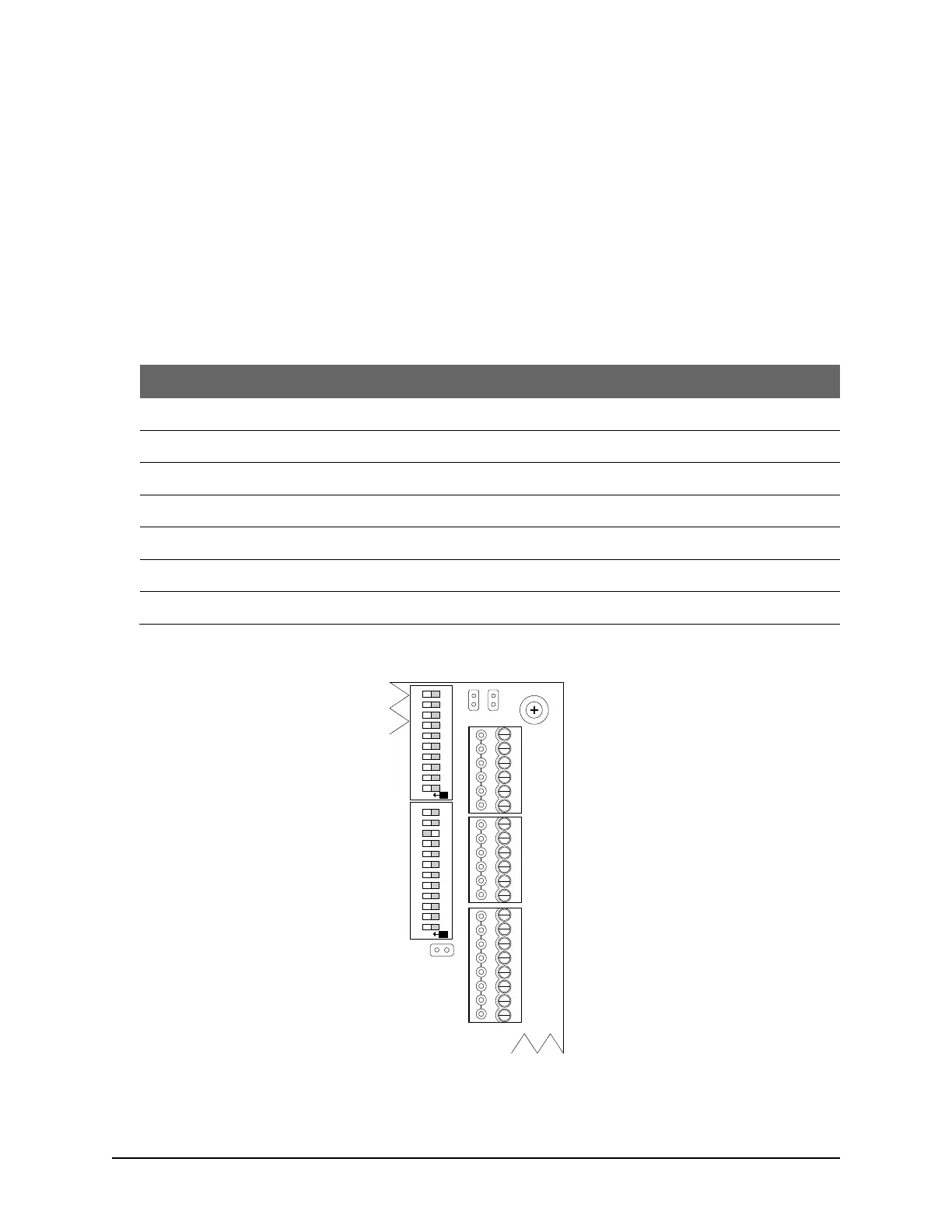
Figure 37 – Control Board Test Points – Voltages
DOOR
RTE AUX1 AUX2
-
+
-
+
-
+
-
+
READER 2
READER 1
C1
(BEEP)
LED
D1
WHITE
D0
GREEN
PWR
RED
GND
BLK
C1
(BEEP)
LED
D1
WHITE
D0
GREEN
PWR
RED
GND
BLK
J4
J1
RDR
RST.
CLR
MEM.
KI-00356E-02-14
SYS.
RST.
RDR/SUPV. CONFIG.SYSTEM CONFIG.
ON
6
7
8
9
10
2
3
4
5
1
6
7
8
9
10
2
3
4
5
1
11 12
ON
S2
S1